Textile machines and false twisting devices

A textile machine, false twisting technology, applied in textile and papermaking, spinning machine, drafting equipment and other directions, can solve the problem of laborious structure and placement, and achieve the effect of low cost

Inactive Publication Date: 2018-09-04
MASCHINENFABRIK RIETER AG
View PDF8 Cites 0 Cited by
  • Summary
  • Abstract
  • Description
  • Claims
  • Application Information

AI Technical Summary

Problems solved by technology

Although the layout is variable, it is of course limited to a single weaving station and can therefore only be placed on the weaving machine with great structural effort

Method used


Image

  • Textile machines and false twisting devices
  • Textile machines and false twisting devices
  • Textile machines and false twisting devices

Examples


Embodiment Construction

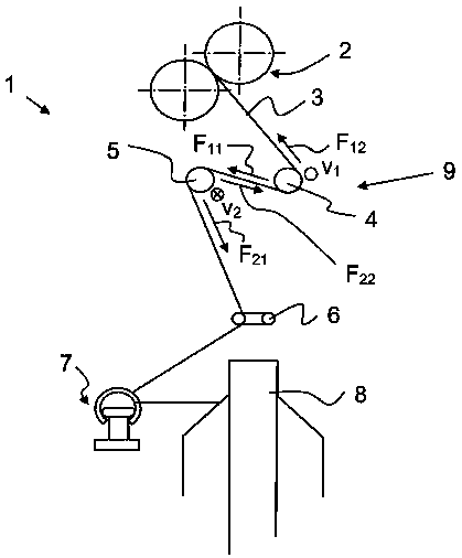
[0031] figure 1 The weaving unit 1 of the weaving machine 10 is partially shown in the schematic diagram. The delivery roll pair 2 of the drafting unit, not shown, supplies the ply strand 3 . The strand 3 turns around a first plastic belt 4 and then around a second plastic belt 5 . Subsequently, the ply yarn 3 passes through the twist stopper 6 and the traveler 7 and is wound on the bobbin 8 . The first plastic belt 4 and the second plastic belt 5 form a false twist device 9 .

[0032]The first plastic belt 4 and the second plastic belt 5 have opposite directions of movement. Since the yarn lies flat on two belts moving in opposite directions, the yarn is stretched in one direction by the return run of one belt and in the other direction by the other belt. The yarn is deflected in the direction of travel until these two frictional forces are balanced. ply line stress F 11 and F 12 and F 21 and F 22 is different. Therefore, the bearing pressure of the strand on one b...


PUM


Abstract

A spinning machine, in particular a ring spinning machine, has a multiplicity of units (1) arranged alongside one another, wherein each unit (1) has a drafting unit for drafting a sliver and a spinning device (10) for twisting the drafted sliver to form a thread (3), and also a false-twist device (9) arranged between the drafting unit and the spinning device (10), said false-twist device (9) being made up of friction faces that extend substantially transversely to the thread (3) and contact the latter. The friction faces of the false-twist device (9) consist of two separate plastics belts (4, 5) which are wrapped in particular in a Z-shaped manner by the thread (3) and are driven in opposite directions by way of a drive device (11, 12; 14). At least one of the belts (4, 5) is guided along a number of the units (1) of the spinning machine (10).

Description

technical field [0001] The invention relates to a textile machine, in particular a ring spinning machine, which has a large number of units arranged side by side, wherein each unit has: a drafting mechanism for transporting a fiber band; a device for twisting the transported fiber band into a ply Textile device; a false twist device arranged between the drafting mechanism and the textile device, which consists of friction surfaces extending substantially transversely to the ply threads and contacting these ply threads; and a corresponding false twist device, which is additionally equipped with on the loom to get this type of loom. Background technique [0002] A textile machine is known from WO 2010 / 015185 A1, in which a false twist device is arranged between a drafting mechanism and a bobbin, on which the fiber strip is twisted and wound on the bobbin. According to an embodiment of the publication there, the false twist device consists of a single belt, which is driven by ...

Claims


Application Information

Patent Timeline
Patent Type & Authority Patents(China)
IPC IPC(8): D01H7/92D01H5/28D02G1/08
CPCD01H7/923D01H5/28D02G1/0206
Inventor G·斯塔莱克S·厄梅特泽
Owner MASCHINENFABRIK RIETER AG
Why Eureka
Try Eureka