Electrical connecting device

An electrical connection device and connection device technology, applied in the direction of connection parts protective grounding/shielding devices, multi-core cable end parts, etc., can solve problems such as unreasonable cable assembly conditions, reduce the overall structure height, and increase installation density Effect

Inactive Publication Date: 2007-06-13
WEIDMULLER INTERFACE GMBH & CO KG
View PDF1 Cites 0 Cited by
  • Summary
  • Abstract
  • Description
  • Claims
  • Application Information

AI Technical Summary

Problems solved by technology

This often results in unreasonable assembly conditions for the cables to be connected

Method used


Image

  • Electrical connecting device
  • Electrical connecting device
  • Electrical connecting device

Examples


Embodiment Construction

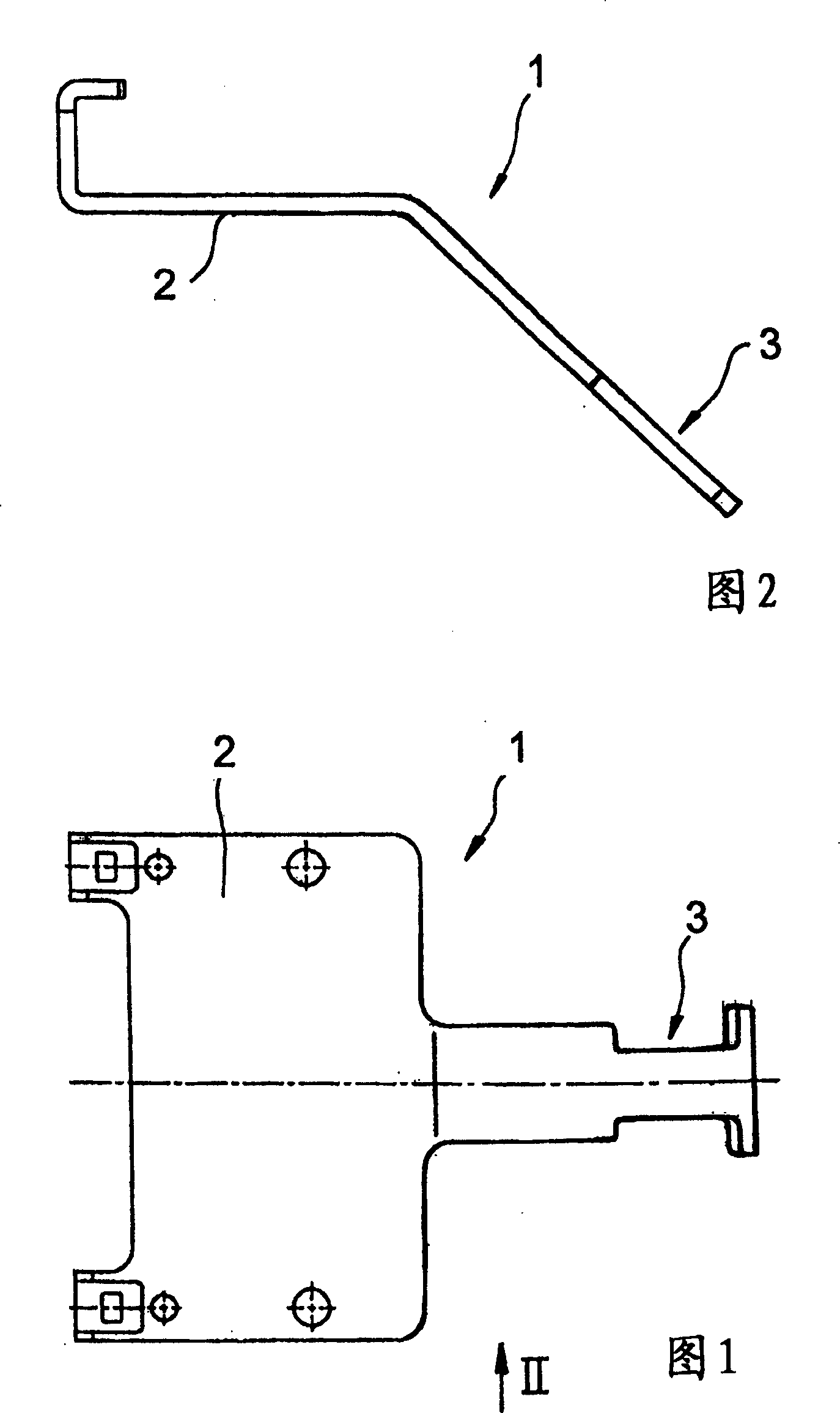
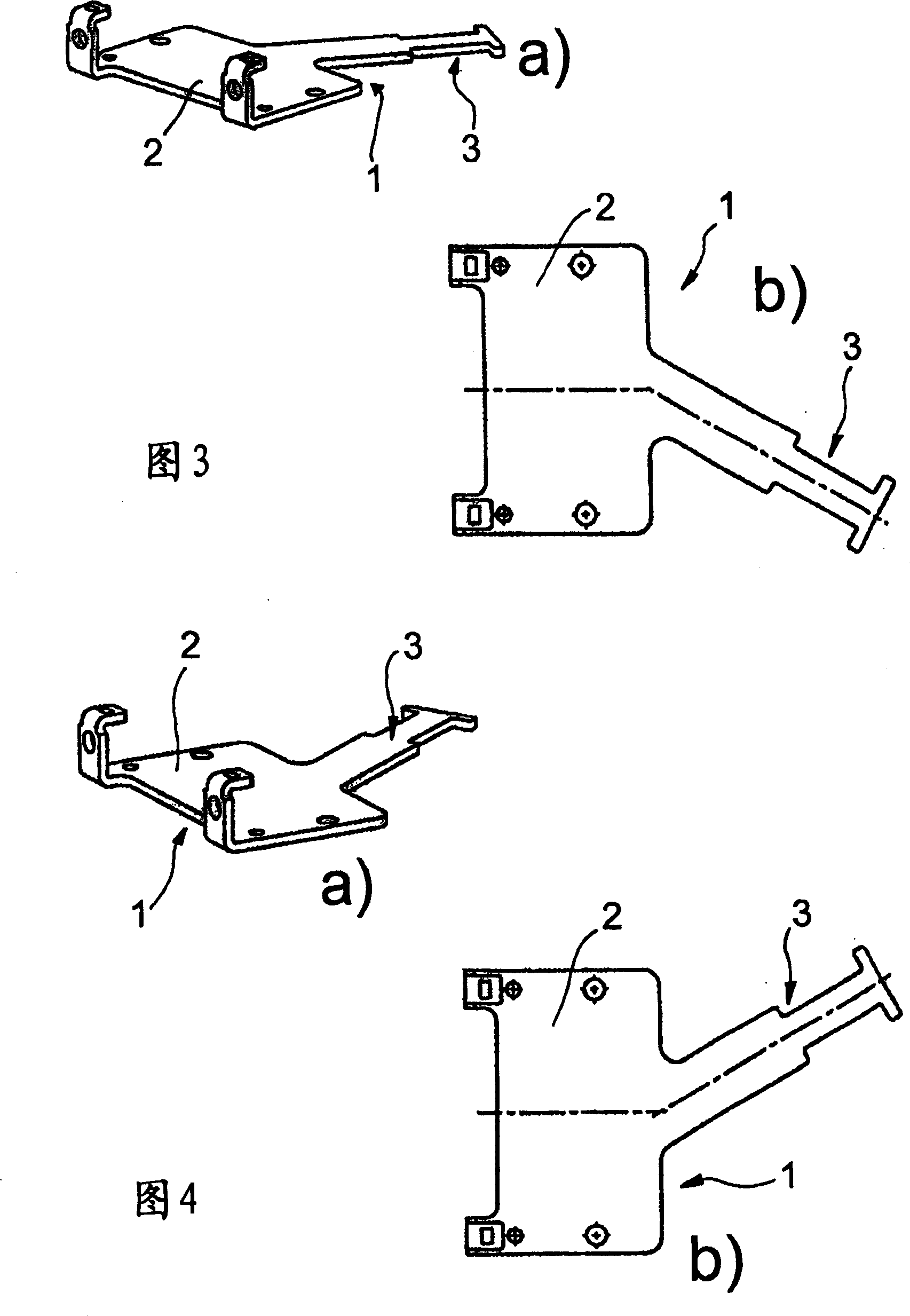
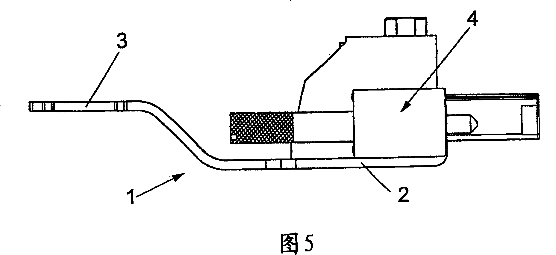
[0015] Electrical connections of this type are well known to those skilled in the art both from practice and from the relevant literature, an exemplary embodiment of which is not shown in its entirety in FIGS. 1 to 4 b.

[0016] In DE 20316262 U1, a plug part is shown and described as an example, which is connected to a shielding plate (referred to in said document as a "shielding connection"). The plug part can be connected to a sleeve part, and the shield plate connected to the plug part is used for connecting the cable.

[0017] For many machines, electronic devices, etc., many corresponding connection devices with corresponding plug parts are required. They are mostly installed side by side and / or overlapped in a distribution box or the like under very crowded conditions. However, unfavorable and congested installation conditions often exist for individual plug parts with shielding plates.

[0018] The structures described above should only be used as examples of connect...


PUM


Abstract

An electrical connection device includes at least a plug member connected with a shielding plate (1) having a mounting board (2) for fixing at least a plug member and a cable connection tongue piece (3) extended from the mounting board for connecting a cable. The connection device is designed for making the cable connection tongue piece (3) of the shielding plate (1) be curved or be gradient distribution correspondingly to a longitudinal central line and/or a plane of the mounting board (2).

Description

technical field [0001] The invention relates to an electrical connection device having at least one plug part connected to a shielding plate, wherein the shielding plate has a mounting plate for fixing the at least one plug part and a mounting plate protruding from the mounting plate for connecting cables cable connection tabs. Background technique [0002] This connecting device can be connected to a shielding plate with a conductor-conductor connection for establishing a shielding or to another plug part with an element without a shielding plate, in which case the shielding plate can be connected to an active part of an electrical or electronic device The ground surface of the electrically conductive housing part or its own counterpart provided for it is conductively connected in order to output interference and balancing currents. [0003] Conductive connections of this type are known, as are found in distribution boxes for machines, electrical installations or also in e...

Claims


Application Information

Patent Timeline
Patent Type & Authority Applications(China)
IPC IPC(8): H01R13/648H01R11/11
Inventor P·维安登G·胡伊斯坎普G·诺伊曼
Owner WEIDMULLER INTERFACE GMBH & CO KG
Why Eureka
Try Eureka