Novel electronic installation cabinet device

A technology for installing cabinets and electronics, which is applied in the direction of support structure installation, clamping/extracting devices, etc., can solve the problems of unstable locking of drawer cabinets, complicated operation of electronic locks, and low maintenance efficiency, so as to improve maintenance and installation efficiency, The effect of increasing the number of locks and unlocks and saving input costs

Inactive Publication Date: 2017-08-01
广州迅速光电科技有限公司
View PDF4 Cites 4 Cited by
  • Summary
  • Abstract
  • Description
  • Claims
  • Application Information

AI Technical Summary

Problems solved by technology

[0003] The locking of the existing electronic installation cabinets is often to set a lock at the front of the drawer for locking, and each drawer is equipped with a lock. When maintenance is required, the drawers are often opened and repaired one by one with a key. , which is very inconvenient for maintenance and low maintenance efficiency, and, due to safety factors, it is necessary to ensure that there is no rigid collision during the unlocking process, so as not to cause heat or even sparks, and the locks used in the existing electronic installation cabinets are of poor quality and are very easy to damage. It makes the lock of the drawer cabinet unstable. Although there are some cabinets with electronic locks installed electronically, the operation of using electronic locks is complicated and the cost of use is high.

Method used


Image

  • Novel electronic installation cabinet device
  • Novel electronic installation cabinet device
  • Novel electronic installation cabinet device

Examples


Embodiment Construction

[0018] The preferred embodiments of the present invention will be described in detail below in conjunction with the accompanying drawings, so that the advantages and features of the present invention can be more easily understood by those skilled in the art, so as to define the protection scope of the present invention more clearly.

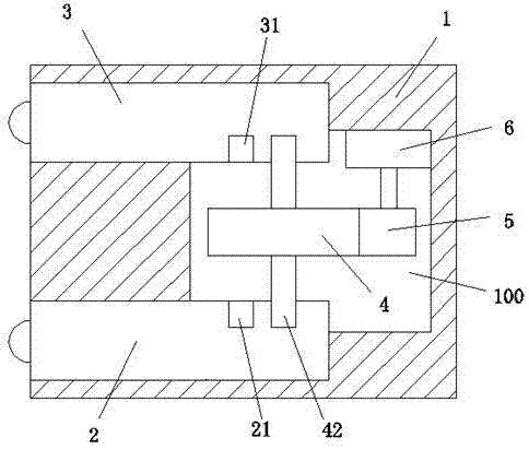
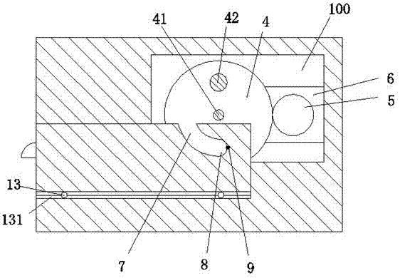
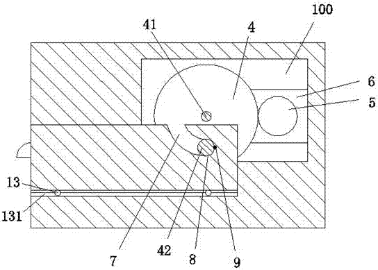
[0019] refer to Figure 1-6 As shown, a novel electronic installation cabinet device of the present invention includes a loading frame 1, and a front mounting drawer 2 and a rear mounting drawer 3 are arranged symmetrically front and back in the loading frame 1, and the rear end surface of the front mounting drawer 2 is close to The right position is provided with a front arc-shaped lock groove 21, and the front end face of the rear installation drawer 3 is provided with a rear arc-shaped lock groove 31 at the right position, and the front arc-shaped lock groove 21 and the rear arc-shaped lock groove 31 The loading rack 1 between is provided with...


PUM


Abstract

The invention discloses a novel electronic installation cabinet device which comprises a loading frame (1). A front mounting drawer (2) and a rear mounting drawer (3) are arranged symmetrically before and after the loading frame (1). A front arcuate lock groove (21) is arranged on the right side of the rear end face of the front mounting drawer (2). A rear arcuate lock groove (31) is arranged on the right side of the front end face of the rear mounting drawer (2). A locking device loading cavity (100) is arranged in the loading frame (1) between the front arcuate lock groove (21) and the rear arcuate lock groove (31). A locking device component is arranged in the locking device loading cavity (100). The locking device component comprises a drive gear (4). The right side of the drive gear (4) is engaged with a pinion (5). The pinion (5) is in power connection with the output shaft of a drive motor (6).

Description

technical field [0001] The invention relates to the fields of electronics and electric power, in particular to a novel electronic installation cabinet device. Background technique [0002] At present, electronic installation cabinets are widely used, and they are often used in the field of electronic control. There are usually various electronic components installed in the drawer-type electronic installation cabinet. In order to facilitate maintenance, the electronic installation cabinet often has drawers to pull out to facilitate maintenance of the electronic components inside. For the lock of the drawer under normal use It is an important measure to ensure the safe operation of power equipment. [0003] The locking of the existing electronic installation cabinets is often to set a lock at the front of the drawer for locking, and each drawer is equipped with a lock. When maintenance is required, the drawers are often opened and repaired one by one with a key. , which is v...

Claims


Application Information

Patent Timeline
Patent Type & Authority Applications(China)
IPC IPC(8): H05K7/14
CPCH05K7/1411H05K7/1414
Inventor 叶翠颖
Owner 广州迅速光电科技有限公司
Why Eureka
Try Eureka