Eureka AIR delivers breakthrough ideas for toughest innovation challenges, trusted by R&D personnel around the world.

Improved new-energy automobile storage battery device

A technology for new energy vehicles and storage battery devices, which is applied in the direction of electric power devices, batteries, coupling devices, etc., and can solve problems such as damage to storage parts, affecting maintenance efficiency, and time-consuming and labor-intensive problems

Inactive Publication Date: 2018-06-29
广州昌源环保科技有限公司
View PDF3 Cites 2 Cited by
  • Summary
  • Abstract
  • Description
  • Claims
  • Application Information

AI Technical Summary

Problems solved by technology

[0002] A new energy electric vehicle is a vehicle that uses a single battery as the energy storage power source. The battery provides electric energy to the motor to drive the car. As the core technology of the new energy electric vehicle, the battery is the core technology of the new energy electric vehicle. Its stability after installation and maintenance after failure The simplicity of maintenance is an urgent problem for new energy electric vehicles. The power storage parts of existing new energy electric vehicles are generally fastened to the cabin by bolts. Excessive tightening force of the bolts will damage the power storage parts and shorten the service life, and the power storage parts need to be disassembled with the help of screwdrivers and other disassembly tools after the power storage parts fail. maintenance efficiency

Method used


Image

  • Improved new-energy automobile storage battery device
  • Improved new-energy automobile storage battery device
  • Improved new-energy automobile storage battery device

Examples


Embodiment Construction

[0025] All the features disclosed in this specification, or all disclosed methods or steps in the process, except for mutually exclusive features and / or steps, can be combined in any manner.

[0026] Any feature disclosed in this specification (including any appended claims, abstract and drawings), unless specifically stated, can be replaced by other equivalent or alternative features with similar purposes. That is, unless otherwise stated, each feature is just one example of a series of equivalent or similar features.

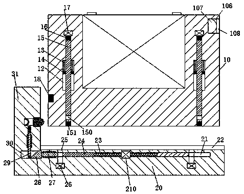
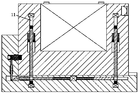
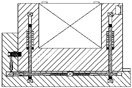
[0027] Such as Figure 1-5 As shown, an improved battery device for a new energy vehicle of the present invention includes a base 20 fixedly arranged in the cabin of an automobile and a mounting box 10 used in conjunction with the base 20, and a mouth is provided in the mounting box 10 The battery 101 is installed in the mounting slot, and the top and left of the battery 101 are correspondingly provided with handles 102. The handle 102 can facilitate the lifting o...


PUM


Abstract

The invention discloses an improved new-energy automobile storage battery device. The improved new-energy automobile storage battery device comprises an engine base and an installing box, wherein theengine base is fixedly arranged in an engine room of an automobile; the installing box is matched with the engine base for use; an installing groove with an upward opening part is formed in the installing box; a storage battery is arranged in the installing groove; handles are arranged at the top part of the storage battery in a left-right corresponding way; first sliding grooves which are in left-right corresponding arrangement and are provided with downward opening parts are formed in the installing box arranged at the left side and the right side of the installing groove; sliding columns which can smoothly slide up and down are arranged in the first sliding grooves; upper magnetic strips and lower magnetic strips are respectively and fixedly arranged on the upper ends and the lower endsof the sliding columns; locking grooves of which the left parts and the right parts are communicated are formed in the lower ends of the sliding columns; first magnetic induction devices are fixedlyarranged in the upper end walls of the first sliding grooves; an electric connecting piece electrically connected with the magnetic induction devices is fixedly arranged on the left end surface of theinstalling box; a clamping groove stretching left and right is formed in the bottom end surface of the installing box.

Description

Technical field [0001] The invention relates to the field of new energy vehicles, in particular to an improved battery device for new energy vehicles. Background technique [0002] A new energy electric vehicle is a car that uses a single battery as the energy storage power source. The battery provides electrical energy to the motor to drive the car. As the core technology of the new energy electric vehicle, the battery is the core technology of the new energy electric vehicle, and its stability after installation and maintenance after failure The ease of maintenance is an urgent problem that new energy electric vehicles need to overcome. The electricity storage parts of existing new energy electric vehicles are generally bolted to the cabin. However, the fixing method by bolts is not only due to Excessive tightening force of the bolts damages the power storage parts and shortens the service life. Moreover, the power storage parts need to be disassembled with the help of disassem...

Claims


Application Information

Patent Timeline
IPC IPC(8): H01M2/10H01R24/00H01R13/71B60K1/04H01M50/249
CPCH01R13/71H01R24/00B60K1/04B60K2001/0455H01R2201/26H01M2220/20H01M50/20Y02E60/10
Inventor 邹科寅
Owner 广州昌源环保科技有限公司
Why Eureka
Eureka Blog
Learn More