

Energy storage facility for thermal energy storage, power plant with energy storage facility and method for operating an energy storage facility
A technology for power stations and facilities, applied to heat storage equipment, lighting and heating equipment, indirect heat exchangers, etc., can solve the problems of reducing the efficiency of energy storage facilities and reducing the temperature of storage media, and achieve small structural space requirements and reliable operation , low-cost effect
Active Publication Date: 2019-07-26
SCHIERACK GREEN TECH GMBH
View PDF6 Cites 0 Cited by
- Summary
- Abstract
- Description
- Claims
- Application Information
AI Technical Summary
Problems solved by technology
But the disadvantage of this is that the temperature of the storage medium (that is, the salt) will decrease during the release of energy
However, this would further reduce the efficiency of the energy storage facility
Method used
View moreImage
Smart ImageViewing Examples

Examples
Embodiment approach
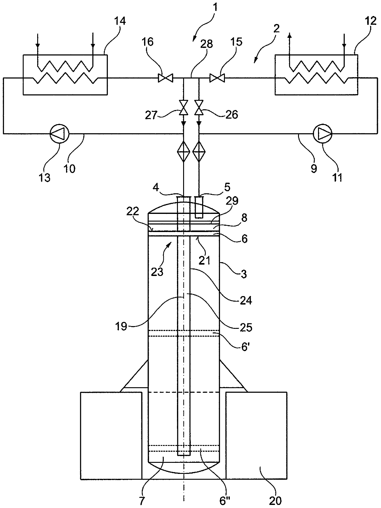
[0081] With the second embodiment of the energy storage installation 1 proposed here, in principle, the same advantages as with the first embodiment can be achieved. By arranging the fluid container 3 vertically, the energy storage installation 1 can be realized with a particularly small base area. Furthermore, the density difference between the cold fluid in the first fluid storage chamber 7 and the hot fluid in the second fluid storage chamber 8 can be utilized when loading and / or unloading the energy storage installation 1 .
Login to View More PUM
 Abstract
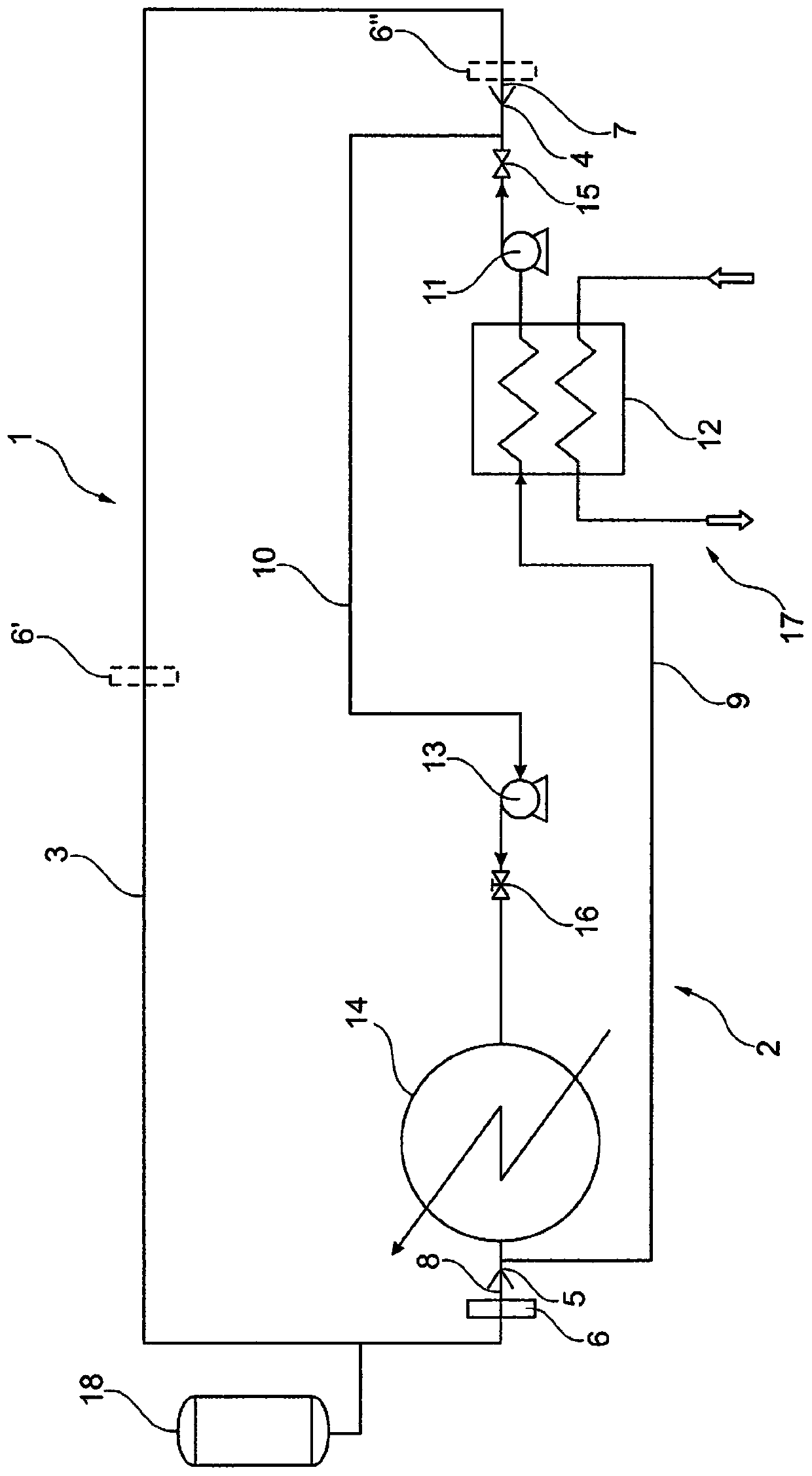
An energy storage device for temporarily storing thermal energy includes a closed storage circuit, to which heat can be supplied by a heat source and from which heat can be withdrawn by a heat consumer. A fluid container is divided into a first fluid storage chamber for colder fluid and a second fluid storage chamber for warmer fluid by a displaceable separating element. The closed storage circuit includes at least one pump for conveying fluid from the first fluid storage chamber into the second fluid storage chamber, and / or vice versa. The energy storage device may be incorporated into a power plant.
Description
technical field [0001] The invention relates to an energy storage facility for thermal energy buffering. Furthermore, the invention relates to a power plant, in particular a solar power plant, a wind power plant or a solar wind power plant, having at least one energy storage facility, and a method for operating the energy storage facility. Background technique [0002] The energy storage facility mentioned at the outset can be used in several fields for buffering thermal energy, i.e. for example loaded with thermal energy during a first period of time and stored at a second period of time immediately following this first period of time heat energy is released in the section. Thus, by means of such an energy storage facility, energy provided by the heat source can be absorbed for a first period of time. During the second time period, the buffered thermal energy is released again in order to supply thermal energy to heat-using objects, for example. [0003] In particular, t...
Claims
Login to View More Application Information
Patent Timeline
 Patent Type & AuthorityPatents(China)
IPC IPC(8): F28D20/00
CPCF28D20/0039F28D2020/0095Y02E60/14
InventorR·霍尔米格H·席拉克
OwnerSCHIERACK GREEN TECH GMBH