Transmission shell, transmission unit, driving unit, and ground transportation tool

A technology for transmission housings and means of transportation, which is applied in the field of transmissions of devices, and can solve problems such as loss of lubricating oil, leakage of lubricating oil, leakage of lubricating oil, etc., and achieve the effect of low cost and small structural space requirements

Inactive Publication Date: 2017-08-08
ZF FRIEDRICHSHAFEN AG
View PDF9 Cites 1 Cited by
  • Summary
  • Abstract
  • Description
  • Claims
  • Application Information

AI Technical Summary

Problems solved by technology

[0006] However, known venting devices for transmission units of ground vehicles are disadvantageous because they unintentionally allow lubricating oil to escape from the transmission housing when venting, or include special additional devices, such as splash guards disk, however the additional installation requires additional construction space and additional costs
Unintentional oil spills not only result in the loss of oil that must be replaced regularly, but are also a burden on the environment

Method used


Image

  • Transmission shell, transmission unit, driving unit, and ground transportation tool
  • Transmission shell, transmission unit, driving unit, and ground transportation tool
  • Transmission shell, transmission unit, driving unit, and ground transportation tool

Examples


Embodiment Construction

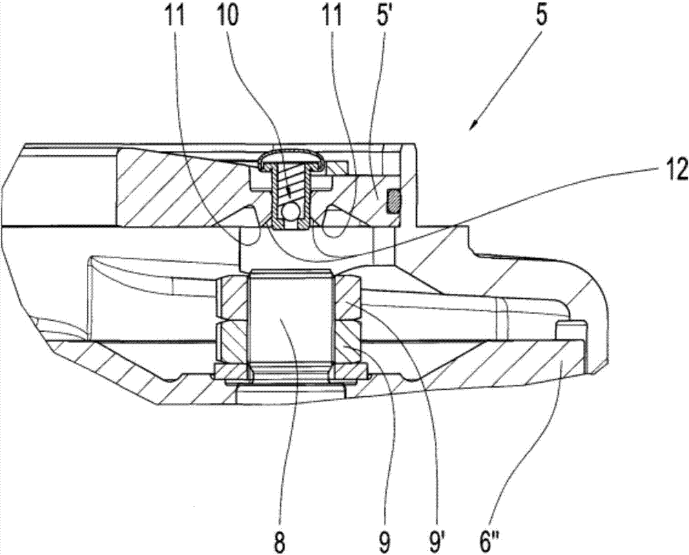
[0036] figure 1 A possible embodiment of the transmission housing 5 according to the invention is shown only partially by way of example. Here, in particular, an upper housing wall 5' can be seen, which has a venting device 10 configured as a spring-loaded non-return valve 10. As can be seen, the exhaust means 10 passes through the upper housing wall 5' from the inside to the outside of the upper housing wall 5'. In this case, directly adjacent to the exhaust device 10, a drip edge 11 is provided on the inner side of the upper housing wall 5', which frames the exhaust device 10 annularly. as by figure 1 It can also be seen from the view that the drip edge 11 is configured as a surface profile on the inner side of the upper housing wall 5', so that it appears as a thorn-like protrusion in the depression 12. According to the example, the depression 12 and the drip edge 11 frame the exhaust device 10 annularly. If, during operation of the drive unit 1 to which the transmissio...


PUM


Abstract

The invention relates to a transmission shell (5) with an exhaust device (10), and the exhaust device (10) penetrates through an upper shell wall (5') of the transmission shell (5) from the inner side of the upper shell wall (5') to the outside of the upper shell wall (5'). The transmission shell (5) is characterized in that the inner side of the upper shell wall (5') and the exhaust device (10) are provided with dripping edges (11) in an adjacent manner.

Description

technical field [0001] The invention relates to a transmission housing with an exhaust device according to the preamble of patent claim 1, a transmission unit for ground vehicles according to the preamble of patent claim 7, a A drive unit for a ground vehicle according to the preamble of patent claim 9 and a ground vehicle according to patent claim 10 . Background technique [0002] Drive units for ground vehicles are known in the prior art. Such a drive unit generally comprises a transmission housing with two transmission stages, a flange-mounted drive motor and a drivable drive wheel. The first transmission stage itself typically includes a drive pinion and a spur gear meshing with the drive pinion, while the second transmission stage typically includes a bevel gear and a ring gear meshing with the bevel gear. Due to the very limited installation space available in ground vehicles, such drive units are subject to severe requirements with regard to their external dimensio...

Claims


Application Information

Patent Timeline
Patent Type & Authority Applications(China)
IPC IPC(8): F16H57/027F16H57/04
CPCF16H57/027F16H57/0424F16H57/04F16H57/0452F16H2057/02034F16H2057/02056
Inventor M·哈贝尔K·宾德
Owner ZF FRIEDRICHSHAFEN AG
Why Eureka
Try Eureka