Cutting equipment

A technology of cutting equipment and ports, which is applied in the field of cutting equipment, can solve problems such as low tightness, loose plug connectors, and poor protection capabilities of plug connectors, and achieve the effect of increasing safety and stability and preventing loose plug connectors

Active Publication Date: 2017-08-04
惠州市摩码鼎力科技有限公司
View PDF6 Cites 2 Cited by
  • Summary
  • Abstract
  • Description
  • Claims
  • Application Information

AI Technical Summary

Problems solved by technology

[0002] Cutting equipment is often used in some workpiece processing and production. In order to facilitate cutting operations, hand-held cutting equipment is the most widely used. Hand-held cutting equipment needs to be connected to electricity during work, and the plug connector setting mode of existing hand-held cutting equipment is too simple. , so that the tightness after plugging is not high, it is very easy to be affected by dragging and pulling the power su

Method used


Image

  • Cutting equipment
  • Cutting equipment
  • Cutting equipment

Examples


Embodiment Construction

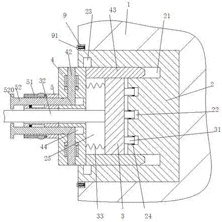
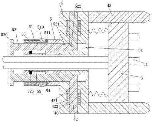
[0019] Combine below Figure 1-5 The present invention will be described in detail.

[0020] refer to Figure 1-5 , a cutting device according to an embodiment of the present invention, including a body 1, a power supply port 2, an electrical connector 3 matched with the power supply port 2, and a supporting device for protecting the electrical connector 3 , the upper and lower sides of the power supply port 2 are provided with threaded blocks 9 at the same time, the threaded blocks 9 are provided with threaded holes, and the threaded holes are fitted with bolts 91, and the power supply port 2 passes through the bolts 91 While being fastened in the body 1, the power supply port 2 is provided with a cavity 25 with the port facing left, and a spring hole 22 is arranged in the right end wall of the cavity 25, and in the spring hole 22 A power supply sheet 24 is provided, the right end of the electrical connector 3 is fixedly provided with an insert spring 31 matching the insert...


PUM


Abstract

Cutting equipment comprises a machine body, a power supply port, an electric connector matched with the power supply port, and a bearing protection device used for protecting the electric connector. A cavity with a leftward port is arranged in the power supply port. An insertion spring hole is formed in the right end wall of the cavity. An insertion spring matched with the insertion spring hole is fixedly arranged at the right end of the electric joint. The bearing protection device comprises a sliding pushing frame which can be in sliding-pushing fit with the cavity and transverse plates correspondingly mounted at the right end of the sliding pushing frame up and down. A shell is fixedly arranged at the left end of the sliding pushing frame. Guiding grooves matched with the transverse plates are correspondingly formed in the right end wall of the cavity up and down. Locking grooves are correspondingly formed in the upper end wall and the lower end wall of the cavity. An extending first sliding groove is correspondingly formed in the sliding pushing frame up and down. Locking arms matched with the locking grooves are movably mounted on the first sliding groove. The shell is provided with a locking device used for driving the locking arms to be cooperated with the locking grooves. An opening device used for relieving cooperation of the locking arms and the locking grooves is arranged on the shell.

Description

technical field [0001] The invention relates to the technical field of cutting, in particular to a cutting device. Background technique [0002] Cutting equipment is often used in some workpiece processing and production. In order to facilitate cutting operations, hand-held cutting equipment is the most widely used. Hand-held cutting equipment needs to be connected to electricity during work, and the plug connector setting mode of existing hand-held cutting equipment is too simple. , so that the tightness after plugging is not high, it is very easy to be affected by dragging and pulling the power supply line during mobile cutting work, which makes the plug connector loose, resulting in poor contact, which has a great impact on the cutting operation, and has great disadvantages , At the same time, the protection ability of the plug joints of the existing handheld cutting equipment is poor. Excessive force or repeated plugging during the plugging process may cause the internal...

Claims


Application Information

Patent Timeline
IPC IPC(8): B25F5/00
CPCB25F5/00
Inventor 周一戈
Owner 惠州市摩码鼎力科技有限公司
Why Eureka
Try Eureka