Series connection type pulse tube heat engine
A series, pulse tube technology, applied in the field of series pulse tube heat engine, can solve the problems of uneven airflow of the regenerator, limited expansion of the intrinsic efficiency of the pulse tube, low efficiency of the regenerator, etc., and avoid uneven airflow. effect of the problem
- Summary
- Abstract
- Description
- Claims
- Application Information
AI Technical Summary
Problems solved by technology
Method used
Image
Examples
Embodiment 1
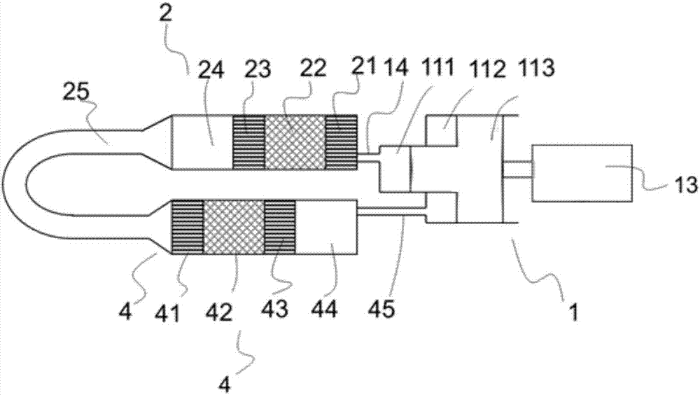
[0036] see figure 1 The series pulse tube heat engine shown is composed of a compressor 1 , a pulse tube unit 2 , a pulse tube unit 4 and an inertia tube 25 .
[0037] Compressor 1 is made up of motor 13, compression chamber 111 and 112, piston 113, and compression chamber 111 and compression chamber 112 do not communicate with each other, and compression chamber 111 links to each other with room temperature heat exchanger 21 in the vascular unit 2 through connecting pipe 14; Lumen 112 , now functioning as an expansion chamber, is connected to vessel 44 in vessel unit 4 via connecting tube 45 .
[0038] In this embodiment, the vascular assembly is composed of a vascular unit 2 , a vascular unit 4 and an inertial tube 25 .
[0039] The pulse tube unit 2 is composed of a room temperature heat exchanger 21 , a regenerator 22 , a high temperature heat exchanger 23 , and a pulse tube 24 connected in sequence, and gas can flow freely in each part.
[0040] The pulse tube unit 4 is...
Embodiment 2
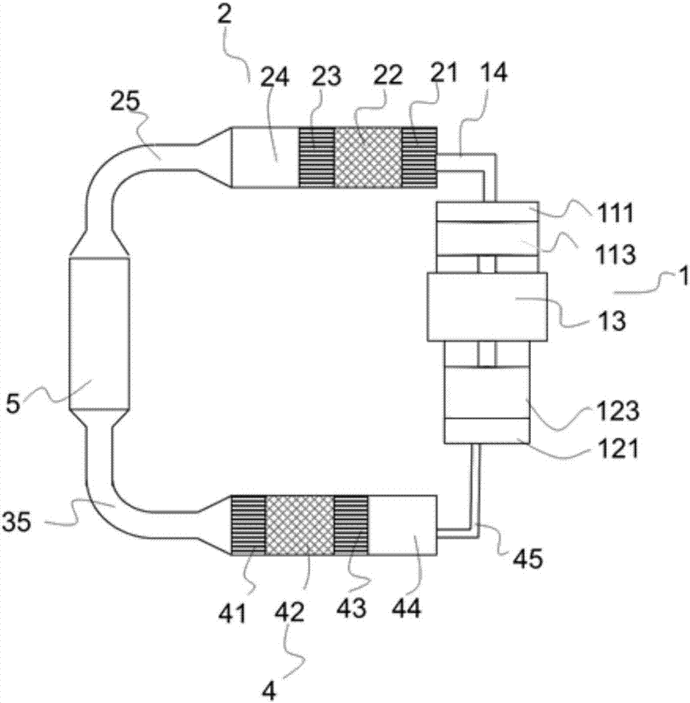
[0051] see figure 2 The series pulse tube heat engine shown is composed of a compressor 1 , a pulse tube unit 2 , a pulse tube unit 4 and a gas storage 5 .
[0052] The compressor 1 is composed of a motor 13, compression chambers 111 and 121, and pistons 113 and 123. The compression chamber 111 and the compression chamber 121 are not communicated with each other, and the compression chamber 111 is connected to the room temperature heat exchanger 21 in the vascular unit 2 through the connecting pipe 14. The compression chamber 121 (acting as an expansion chamber at this time) is connected to the vessel 44 in the vessel unit 4 through the connecting tube 45 . Pistons 113 and 123 move in phase.
[0053] The pulse tube unit 2 is formed by sequentially connecting a room temperature heat exchanger 21 , a regenerator 22 , a high temperature heat exchanger 23 and a pulse tube 24 , and gas can flow freely in each component.
[0054] The pulse tube unit 4 is formed by sequentially co...
Embodiment 3
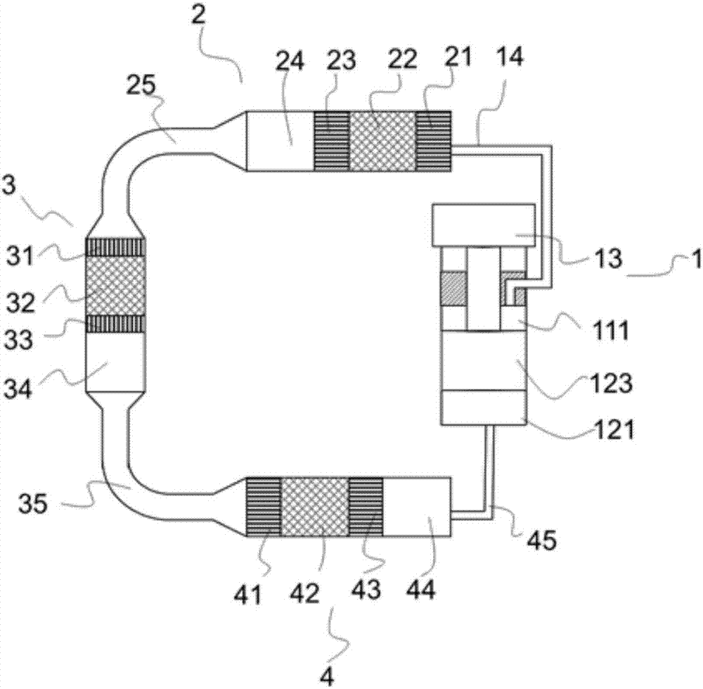
[0060] see image 3 The series pulse tube heat engine shown is composed of a compressor 1 , a pulse tube unit 2 , a pulse tube unit 3 and a pulse tube unit 4 .
[0061] Compressor 1 is made up of motor 13, compression chamber 111 and 121, piston 123, and compression chamber 111 and compression chamber 121 are not communicated with each other, and compression chamber 111 links to each other with the room temperature heat exchanger 21 in the vascular unit 2 by connecting pipe 14; The lumen 121 , now functioning as an inflation lumen, is connected to the vessel 44 in the vessel unit 4 via a connecting tube 45 .
[0062] The pulse tube unit 2 is formed by sequentially connecting a room temperature heat exchanger 21 , a regenerator 22 , a high temperature heat exchanger 23 and a pulse tube 24 , and gas can flow freely in each part.
[0063] The pulse tube unit 3 is formed by sequentially connecting a room temperature heat exchanger 31 , a regenerator 32 , a high temperature heat e...
PUM
 Abstract
Description
Claims
Application Information
 - R&D
- Intellectual Property
- Life Sciences
- Materials
- Tech Scout
- Unparalleled Data Quality
- Higher Quality Content
- 60% Fewer Hallucinations
Browse by: Latest US Patents, China's latest patents, Technical Efficacy Thesaurus, Application Domain, Technology Topic, Popular Technical Reports.
© 2025 PatSnap. All rights reserved.Legal|Privacy policy|Modern Slavery Act Transparency Statement|Sitemap|About US| Contact US: help@patsnap.com


