A series pulse tube heat engine

A series and pulse tube technology, which is applied in the direction of refrigerators, compressors, gas cycle refrigerators, etc., can solve the problems of uneven air flow in the regenerator, large re-elongation resistance, and low efficiency of the regenerator, so as to avoid The effect of uneven airflow problems

Active Publication Date: 2019-12-03
TONGJI UNIV
View PDF3 Cites 0 Cited by
  • Summary
  • Abstract
  • Description
  • Claims
  • Application Information

AI Technical Summary

Problems solved by technology

[0003] However, the flow characteristics of the vessel and its intrinsic efficiency limit its application to high power
[0004] The existing Stirling pulse tube heat engine cannot be made very large. The reason is that when the power is high, the diameter of the regenerator becomes larger, and the length is limited by the resistance of the regenerator. The general length is 40-100mm, and the resistance is too large if it is longer.
The airflow inside the stubby regenerator is severely uneven, and the efficiency of the regenerator is very low

Method used


Image

  • A series pulse tube heat engine
  • A series pulse tube heat engine
  • A series pulse tube heat engine

Examples


Embodiment 1

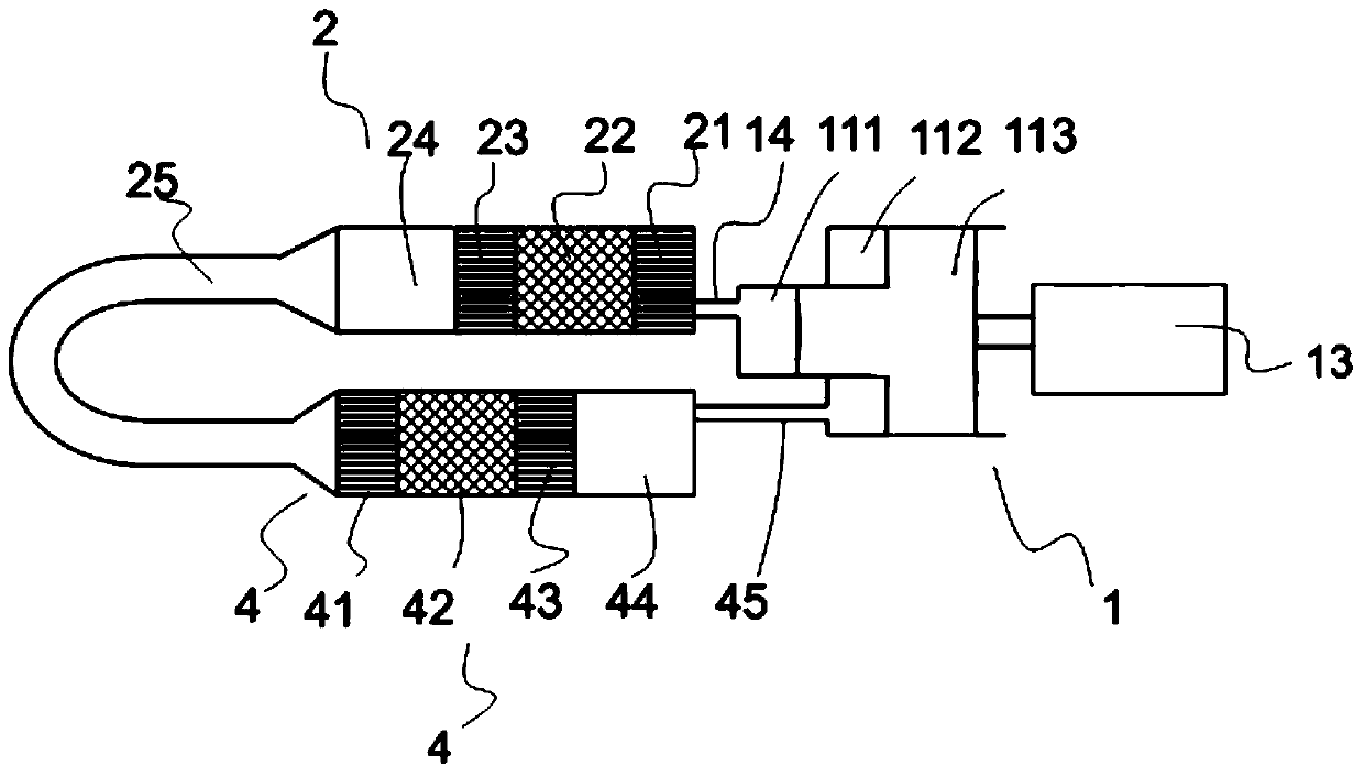
[0036] see figure 1 The series pulse tube heat engine shown is composed of a compressor 1 , a pulse tube unit 2 , a pulse tube unit 4 and an inertia tube 25 .

[0037] Compressor 1 is made up of motor 13, compression chamber 111 and 112, piston 113, and compression chamber 111 and compression chamber 112 do not communicate with each other, and compression chamber 111 links to each other with room temperature heat exchanger 21 in the vascular unit 2 through connecting pipe 14; Lumen 112 , now functioning as an expansion chamber, is connected to vessel 44 in vessel unit 4 via connecting tube 45 .

[0038] In this embodiment, the vascular assembly is composed of a vascular unit 2 , a vascular unit 4 and an inertial tube 25 .

[0039] The pulse tube unit 2 is composed of a room temperature heat exchanger 21 , a regenerator 22 , a high temperature heat exchanger 23 , and a pulse tube 24 connected in sequence, and gas can flow freely in each part.

[0040] The pulse tube unit 4 is...

Embodiment 2

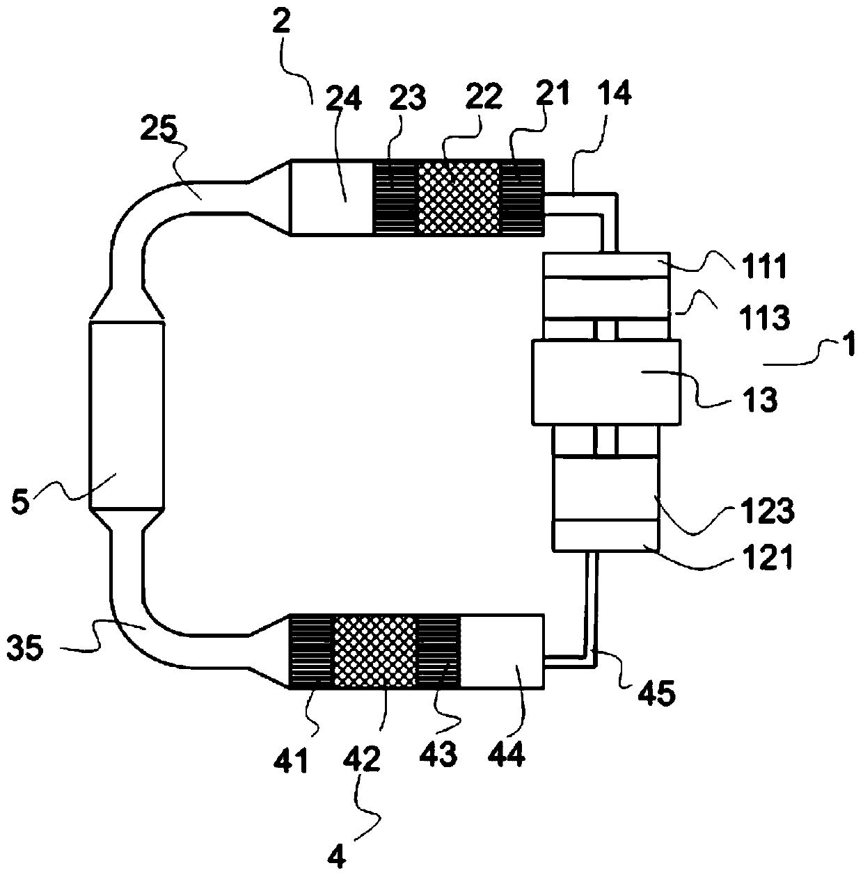
[0051] see figure 2 The series pulse tube heat engine shown is composed of a compressor 1 , a pulse tube unit 2 , a pulse tube unit 4 and a gas storage 5 .

[0052] The compressor 1 is composed of a motor 13, compression chambers 111 and 121, and pistons 113 and 123. The compression chamber 111 and the compression chamber 121 are not communicated with each other, and the compression chamber 111 is connected to the room temperature heat exchanger 21 in the vascular unit 2 through the connecting pipe 14. The compression chamber 121 (acting as an expansion chamber at this time) is connected to the vessel 44 in the vessel unit 4 through the connecting tube 45 . Pistons 113 and 123 move in phase.

[0053] The pulse tube unit 2 is formed by sequentially connecting a room temperature heat exchanger 21 , a regenerator 22 , a high temperature heat exchanger 23 and a pulse tube 24 , and gas can flow freely in each component.

[0054] The pulse tube unit 4 is formed by sequentially co...

Embodiment 3

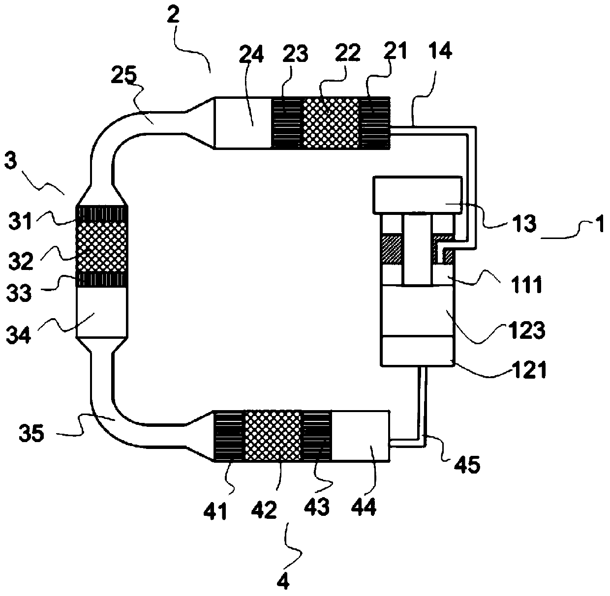
[0060] see image 3 The series pulse tube heat engine shown is composed of a compressor 1 , a pulse tube unit 2 , a pulse tube unit 3 and a pulse tube unit 4 .

[0061] Compressor 1 is made up of motor 13, compression chamber 111 and 121, piston 123, and compression chamber 111 and compression chamber 121 are not communicated with each other, and compression chamber 111 links to each other with the room temperature heat exchanger 21 in the vascular unit 2 by connecting pipe 14; The lumen 121 , now functioning as an inflation lumen, is connected to the vessel 44 in the vessel unit 4 via a connecting tube 45 .

[0062] The pulse tube unit 2 is formed by sequentially connecting a room temperature heat exchanger 21 , a regenerator 22 , a high temperature heat exchanger 23 and a pulse tube 24 , and gas can flow freely in each part.

[0063] The pulse tube unit 3 is formed by sequentially connecting a room temperature heat exchanger 31 , a regenerator 32 , a high temperature heat e...


PUM


Abstract

The invention relates to a series connection type pulse tube heat engine. The series connection type pulse tube heat engine comprises a series connection pulse tube assembly and a compressor, wherein the series connection pulse tube assembly is formed by series connection of a plurality of pulse tube units and an inertance tube; each pulse tube unit comprises a room temperature heat exchanger, a heat regenerator, a high-temperature heat exchanger and a pulse tube which are in sequential connection; the compressor comprises at least two compressing cavities; and one of the two compressing cavities communicates with the room temperature heat exchanger of the pulse tube unit at the head end, and the other compressing cavity communicates with the pulse tube of the pulse tube unit at the tail end. The series connection type pulse tube heat engine disclosed by the invention can operate in four modes, and the four modes are respectively a refrigerator mode, a heat pump mode, a thermomotor mode and a cold engine mode. Compared with the prior art, the series connection type pulse tube heat engine adopts several series connection type pulse tube units to achieve the purpose of being high in power, so that the problem that under high power, the air current is uneven caused by the short and thick heat regenerator is solved.

Description

technical field [0001] The invention relates to a pulse tube heat engine, in particular to a series pulse tube heat engine. Background technique [0002] Pulse tube refrigerators have been applied in aerospace, which is characterized by small cooling capacity and long life. There are two types of pulse tube refrigerators, the form without recovery of expansion work and the form of recovery of expansion work. In the form of recovering expansion work, the stepped compressor or double-acting compressor pulse tube heat engine is the simplest, and it has only one moving part, and its theoretical efficiency can be the same as that of the Carnot heat engine. Because it is a reversible heat engine, it can operate in four modes: refrigerator, heat pump, heat engine, and cold engine. Compared with the Stirling engine, its structure and operation are extremely simple. It would be very useful if it could be increased in power. [0003] However, the flow characteristics of the vessel...

Claims


Application Information

Patent Timeline
Patent Type & Authority Patents(China)
IPC IPC(8): F25B9/14
CPCF25B9/145F25B2309/1412
Inventor 朱绍伟
Owner TONGJI UNIV
Why Eureka
Try Eureka