Input device

An input device and input operation technology, applied in the input/output process of data processing, instruments, electrical digital data processing, etc., can solve the problems of complex structure and large number of components, and achieve the effect of simple structure

Inactive Publication Date: 2017-08-04
ALPS ALPINE CO LTD
View PDF8 Cites 0 Cited by
  • Summary
  • Abstract
  • Description
  • Claims
  • Application Information

AI Technical Summary

Problems solved by technology

Therefore, there are disadvantages of a large

Method used


Image

  • Input device
  • Input device
  • Input device

Examples


Embodiment Construction

[0040] Hereinafter, an input device according to an embodiment of the present invention will be described with reference to the drawings.

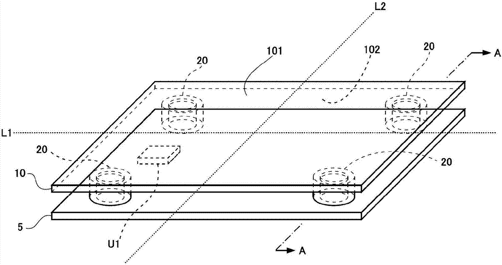
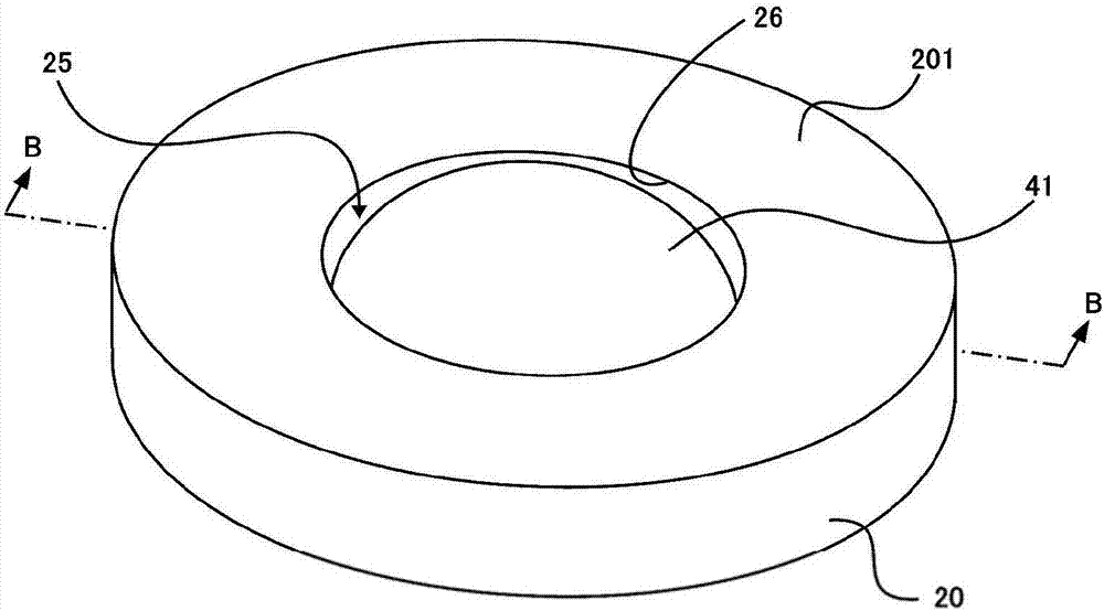
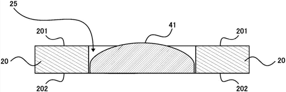
[0041] figure 1 It is a figure which shows an example of the structure of the input device of this embodiment. figure 1 The shown input device has a substrate 10 for receiving input operations and four support portions 20 elastically supporting the substrate 10 , and inputs information corresponding to various input operations performed by touching the substrate 10 with a finger, a pen, or the like. This input device has a function of detecting a force applied to the substrate 10 and a function of detecting the position of an object approaching the substrate 10 as a detection function for inputting information corresponding to an input operation.

[0042] Substrate 10 in figure 1 In the example shown in FIG. The substrate 10 accepts input operations on the first surface 101 . In addition, in figure 1 In the example shown above, the pl...


PUM


Abstract

To provide an input device that detects force applied to a substrate as input operation is performed with simple constitution and decreases the number of components. When force is applied to a substrate 10 as input operation is performed, a housing space 25 varies elastically in capacity and a conductive member 41 as an elastic member housed in the housing space 25 is caused to elastically deform. According to the elastic deformation of the conductive member 41, a variable resistance part 43 varies in resistance value and a signal generated by a signal generation part changes. The need for a mechanism component such as a spacer etc., for forming a gap between electrodes is eliminated, and a mechanism component which causes displacement and elastic deformation for detecting force need not be provided separately from a support part 20. The number of members is reduced, and the structure is simplified.

Description

technical field [0001] The present invention relates to an input device that detects an input operation such as pressing a substrate. Background technique [0002] Patent Document 1 describes an input device including a proximity sensor that detects the approach of an object and a force sensor (load cell) that detects a force applied from the outside. In this conventional input device, both the proximity sensor and the force sensor perform sensing and detection based on changes in electrostatic capacitance. A conventional input device has a first substrate and a second substrate. Electrodes for the proximity sensor are arranged on the front surface of the first substrate, and electrodes for the force sensor are arranged on the back surface thereof. In addition, the second substrate is bonded to the back surface of the first substrate via a spacer layer. The second substrate is a metal plate having a spring mechanism and electrode elements formed by press working. The ele...

Claims


Application Information

Patent Timeline
IPC IPC(8): G06F3/041G06F3/044H03K17/975
CPCG06F3/0414G06F3/044G06F2203/04105H03K17/975
Inventor 重高宽
Owner ALPS ALPINE CO LTD
Why Eureka
Try Eureka