Composite pipe welding mechanism

A composite material tube and welding mechanism technology, which is applied in the direction of tubular articles, other household appliances, household appliances, etc., can solve the problems of unguaranteed welding quality and low welding efficiency, and achieve the effect of convenient and intelligent operation and realization of intelligent operation.

Inactive Publication Date: 2017-08-11
SHENZHEN FORESIGHT ELECTRICAL
View PDF5 Cites 10 Cited by
  • Summary
  • Abstract
  • Description
  • Claims
  • Application Information

AI Technical Summary

Problems solved by technology

[0003] There is no integrated welding structure in the prior art. This kind of welding adopts welding pads and planers to be set separately. The angle and position of the c

Method used


Image

  • Composite pipe welding mechanism
  • Composite pipe welding mechanism
  • Composite pipe welding mechanism

Examples


Embodiment Construction

[0045] The present invention will be described in detail below in conjunction with the accompanying drawings.

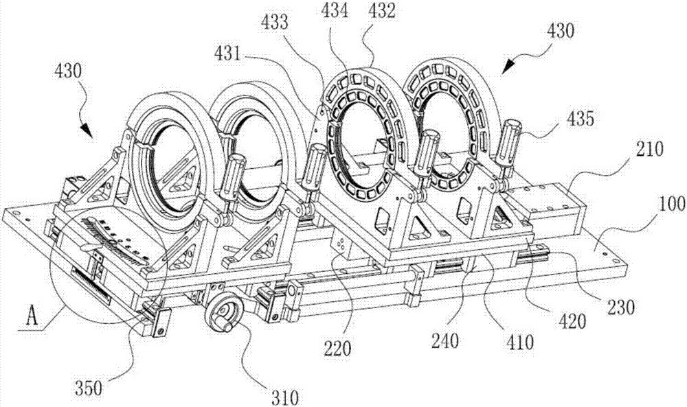
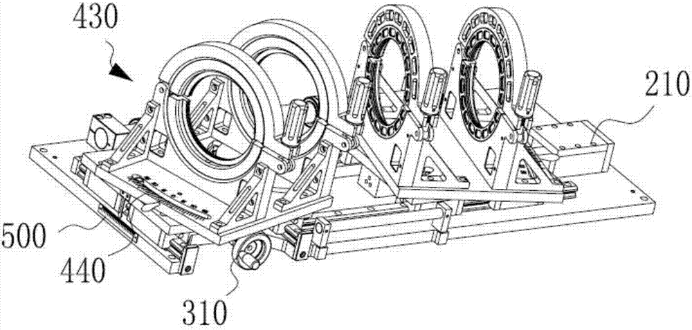
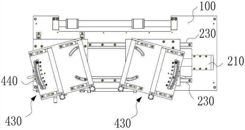
[0046] Such as Figure 1-Figure 10 As shown, this embodiment provides a composite material pipe welding mechanism 20, which is installed on the side of the pipe angle positioning mechanism 10. The pipe angle positioning mechanism 10 includes a hoop assembly 430 for clamping two pipes to be welded. The composite material The pipe welding mechanism 20 includes a guide structure arranged horizontally, and a pad support 21 is installed on the guide structure. The main body 22 ; the first end of the pad support 21 can translate along the guide structure, and the pad support 21 can rotate around the guide structure and drive the pad main body 22 to rotate between the two hoop assemblies 430 .

[0047] Such as Figure 8 As shown, the tube angle positioning mechanism 10 in this mechanism can clamp two sections of tubes, and can properly adjust the angle between the axes of...


PUM


Abstract

The invention relates to the field of welding, in particular to a composite pipe welding mechanism. The composite pipe welding mechanism is mounted on the side face of a pipe angle positioning mechanism, and the pipe angle positioning mechanism comprises anchor ear components used for clamping two pipes to be welded. The composite pipe welding mechanism comprises a horizontal guide structure, and a welding plate support is arranged on the guide structure. The first end of the welding plate support is arranged on the guide structure, and a main welding plate body of which the end face is a welding face is arranged on a main welding plate support body. The first end of the welding plate support can translate along the guide structure, and the welding plate support can rotate around the guide structure and drive the main welding plate body to rotate to the position between the two anchor ear components. Through the guide structure, a welding structure can be handheld to move on an operating platform and rotates to the suitable position after moving in place. The welding mechanism can integrate welding, planer tool and angle adjusting mechanisms in one, does not need additional adjustment and docking before welding, and meanwhile is convenient to realize intelligent operation.

Description

technical field [0001] The invention relates to the welding field, in particular to a composite material pipe welding angle positioning mechanism. Background technique [0002] PE pipe welding mainly includes material preparation: the roundness of the pipe used for welding pipe fittings should be higher than the standard value, and a cutting allowance of 10-20mm should be reserved when cutting the material. When used for pipeline connection, the two pipes to be welded should be placed on a flat ground to clamp the pipes. Replace the basic clamps according to the pipes to be welded, and select the appropriate slips. The welded pipe sections must be clamped before cutting. Cutting: cutting the impurities and oxide layer on the end face of the welded pipe section to ensure that the two butt end faces are smooth and clean. Alignment: The misalignment of two butt-welded pipe sections should be as small as possible. If the misalignment is large, it will lead to stress concentrati...

Claims


Application Information

Patent Timeline
IPC IPC(8): B29C65/20B29C65/78B29K23/00B29L23/00
CPCB29C65/2061B29C65/2092B29C65/7841B29K2023/06B29L2023/22B29C65/7802B29C66/02241B29C66/1142B29C66/1162B29C66/5221B29C66/5223B29C66/71B29C66/73921B29C66/861
Inventor 黄启航
Owner SHENZHEN FORESIGHT ELECTRICAL
Why Eureka
Try Eureka