Eureka AIR delivers breakthrough ideas for toughest innovation challenges, trusted by R&D personnel around the world.

Switch core part structure capable of preventing action dead point

A technology of switch core and dead point, applied in the direction of electric switches, electrical components, emergency springs, etc., can solve problems such as wrong action, flickering, and machine damage of machinery and equipment

Active Publication Date: 2017-08-11
ZHANGZHOU JUANMEI ELECTRIC TECH CO LTD
View PDF5 Cites 1 Cited by
  • Summary
  • Abstract
  • Description
  • Claims
  • Application Information

AI Technical Summary

Problems solved by technology

[0002] Most of the existing limit switch cores are in the form of springs or shrapnel. When the switch moving contact piece changes from normally closed contact to normally open contact, it is prone to non-conduction or signal flickering. The machine is damaged. Using it on the elevator may cause the elevator to stop or start unexpectedly. Using it on the train will cause the door to fail to open, and passengers need to evacuate urgently.
[0003] At present, the solution to this problem is mostly to make the normally open and normally closed metal moving contacts into movable structures, and then use a small spring between the two moving contacts to position them on both ends of the moving contact plastic bracket. The action force generated is far greater than the force of the small spring. The contact of the normally closed movable contact contacts the contact of the normally closed connector and creates a gap with the plastic bracket of the movable contact near the end of the normally closed movable contact. This gap is used to offset the switching action. The small gap generated at the critical position leads to power failure or flickering. Because the switch needs to withstand a relatively large current, there is a requirement for the gap between the moving and static contacts, and the resulting gap will be added to the gap between the moving and static contacts. The problem caused by this method is The action parameters of the switch are much larger than those without a small spring. In order to ensure the safety and reliability of the switch, it is necessary to increase the action stroke and the total stroke. The deformation of the seal rubber corresponding to the external switch trigger mechanism is also small when there is a seal. It will be relatively large. As time goes by and the number of actions increases, it will easily lead to rubber fatigue and rupture. There are international standards for the size of the installation hole of the switch itself. The switch cavity also needs to have enough space for external wire connector connections, which determines The switch core cannot be made very large, which also determines that the return spring cannot be made very long, and a large amount of compression is required in a limited length, which may easily lead to spring fatigue and fracture
Another problem brought about by this method is that the moving contact piece is positioned with a small spring. The position of the moving contact piece is easy to change in the external vibration environment and the switch itself, which leads to large changes in the accuracy and action parameter tolerance of the switch.

Method used


Image

  • Switch core part structure capable of preventing action dead point
  • Switch core part structure capable of preventing action dead point
  • Switch core part structure capable of preventing action dead point

Examples


Embodiment 1

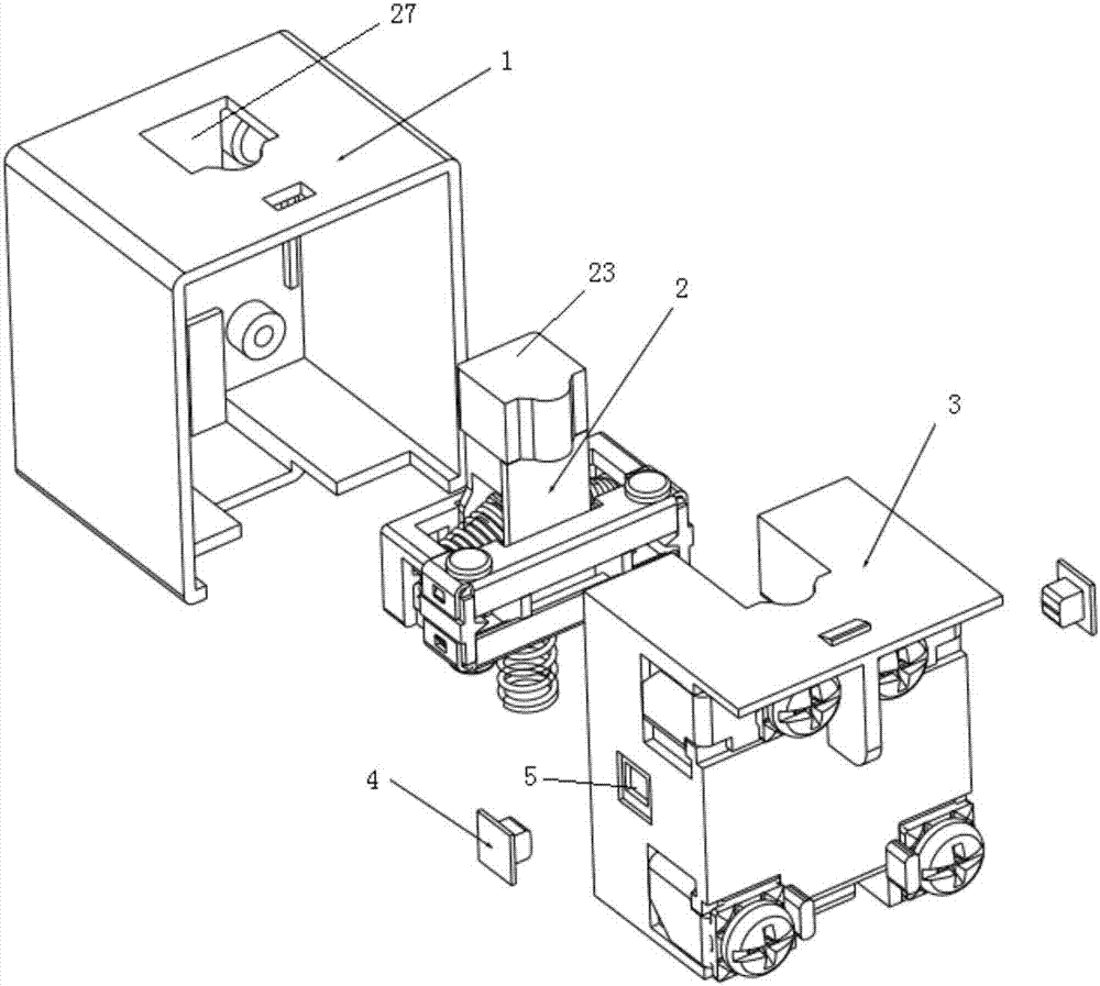
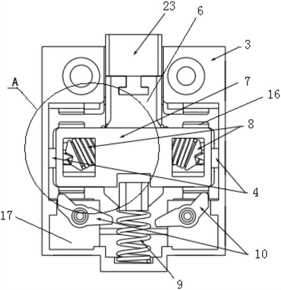
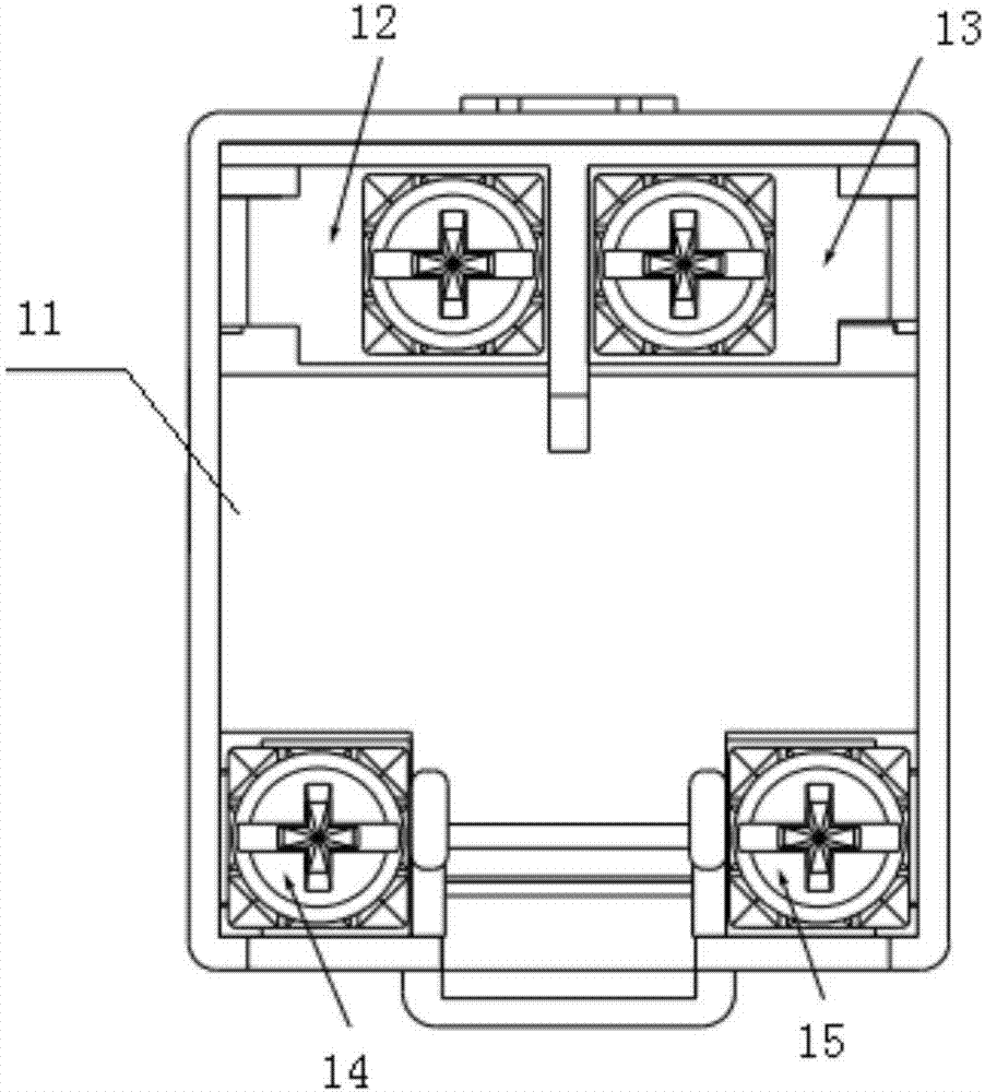
[0031] like figure 1As shown, a switch core structure to prevent action dead point includes a base 1, a base assembly 3 and a movable assembly 2, the base assembly 3 and the base 1 are rectangular cover structures, the base assembly 3 and the base 1. The opening surface is relatively socketed, and the base 1 is socketed on the periphery of the base assembly 3; the movable assembly 2 is arranged between the base 1 and the base assembly 3, and the top surface of the base 1 is provided with a hole 27; the base assembly 3 It includes a lower cover 11, a left normally open socket assembly 12, a right normally open socket assembly 13, a left normally closed socket assembly 14 and a right normally closed socket assembly 15. The two sides of the lower cover 11 are respectively provided with corresponding rectangular Holes 5 and rectangular holes 5 are inlaid with positioning blocks 4, and the opposite faces of the two positioning blocks 4 are slope structures with a high middle and lo...


PUM


Abstract

The invention discloses a switch core part structure capable of preventing an action dead point. The switch core part structure comprises a base, a base assembly and a movable assembly; a pass-through hole is formed in the top surface of the base; the base assembly comprises a lower cover, a left normally-open connecting-inserting assembly, a right normally-open connecting-inserting assembly, a left normally-closed connecting-inserting assembly and a right normally-closed connecting-inserting assembly; rectangular holes are formed in the two side edges of the lower cover; positioning blocks are embedded on the rectangular holes respectively; the movable assembly comprises a movable rod, a pressing block, elastic assemblies, a movable contact piece base, a movable contact piece and a reset spring; a groove is formed in the top end of the movable rod; a convex block is arranged at the bottom end of the pressing block; the convex block is embedded in the groove; the reset spring is arranged below the movable contact piece base; the bottom end of the movable rod is connected with the top end of the reset spring; the elastic assemblies are connected with the two sides of the movable rod; through holes are formed in the side walls of the movable contact piece base; the elastic assemblies passes through the through holes to be in contact with the corresponding positioning blocks; and the movable contact piece is arranged on the movable contact piece base. By virtue of the switch core part structure, the phenomena of signal flickering or power failure can be solved, and switch action parameters and repeated precision can be improved.

Description

technical field [0001] The invention relates to a switch, in particular to a switch core structure for preventing action dead point. Background technique [0002] Most of the existing limit switch cores are in the form of springs or shrapnel. When the switch moving contact piece changes from normally closed contact to normally open contact, it is prone to non-conduction or signal flickering. The machine is damaged. Using it on the elevator may cause the elevator to stop or start unexpectedly. Using it on the train will cause the door to fail to open, and passengers need to evacuate urgently. [0003] At present, the solution to this problem is mostly to make the normally open and normally closed metal moving contacts into movable structures, and then use a small spring between the two moving contacts to position them on both ends of the moving contact plastic bracket. The action force generated is far greater than the force of the small spring. The contact of the normally c...

Claims


Application Information

Patent Timeline
Patent Type & Authority Applications(China)
IPC IPC(8): H01H13/28
CPCH01H13/285H01H2235/004H01H2235/01
Inventor 戴四川
Owner ZHANGZHOU JUANMEI ELECTRIC TECH CO LTD
Why Eureka
Eureka Blog
Learn More