Image correction method and device for projection equipment

A projection device and image correction technology, applied in the field of image processing, can solve problems such as content deformation and affecting users' viewing

Active Publication Date: 2017-08-15
HISENSE BROADBAND MULTIMEDIA TECH
View PDF6 Cites 12 Cited by
  • Summary
  • Abstract
  • Description
  • Claims
  • Application Information

AI Technical Summary

Problems solved by technology

[0005] In order to solve the problem that the correction of the trapezoidal display area cannot be realized in the prior art, resulting in deformation of the projected display content and affecting the viewing of the user, an embodiment of the present invention provides an image correction method and device for a projection device

Method used


Image

  • Image correction method and device for projection equipment
  • Image correction method and device for projection equipment
  • Image correction method and device for projection equipment

Examples


Embodiment Construction

[0027] In order to make the object, technical solution and advantages of the present invention clearer, the implementation manner of the present invention will be further described in detail below in conjunction with the accompanying drawings.

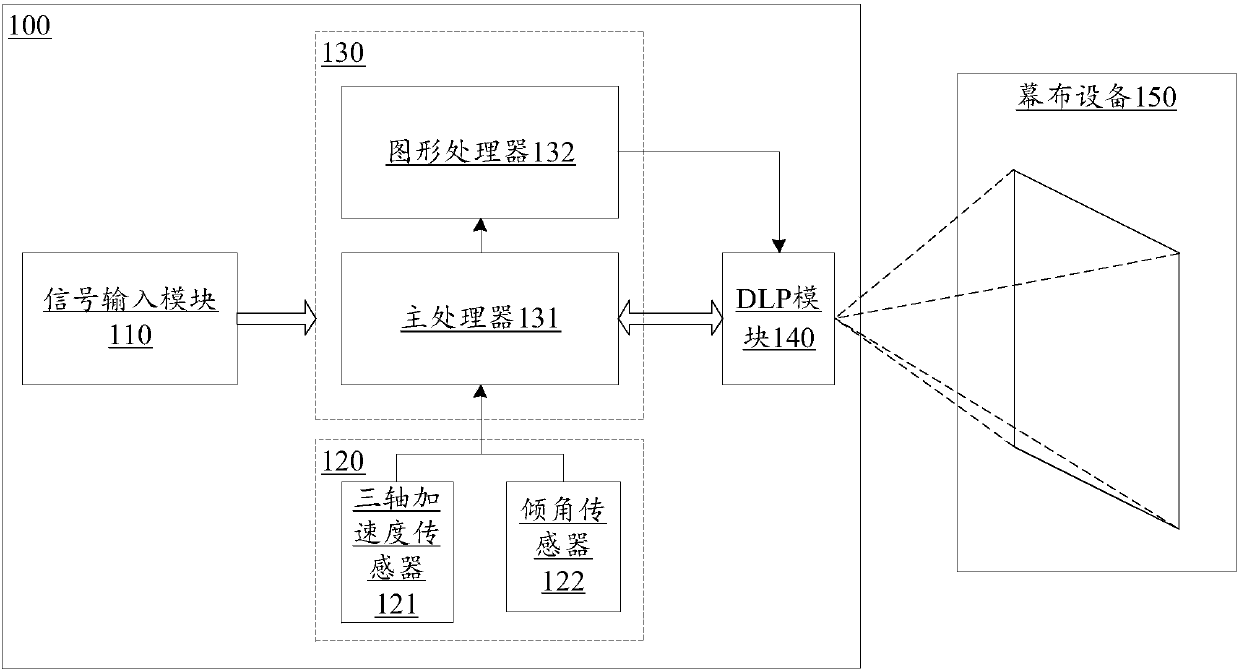
[0028] In order to facilitate the reader's understanding of the various embodiments of the present invention, first combined Figure 1A Introduction to projection equipment. Figure 1A is a structural block diagram of a projection system shown in an embodiment of the present invention, such as Figure 1A As shown, the projection system mainly includes: a projection device 100 and a screen device 150 .

[0029] The projection device 100 includes a signal input module 110 , a sensor module 120 , a processing module 130 and a DLP module 140 .

[0030] The signal input module 110 is used to provide an interface for signal input, such as: HDMI (High Definition Multimedia Interface, high-definition multimedia interface), AV (Audio&Video, home...


PUM


Abstract

The invention discloses an image correction method and device for projection equipment, and belongs to the technical field of image processing. The method comprises the following steps: acquiring n sampling coordinates of an input image and placement direction information of the projection equipment, wherein n is a positive integer, and the sampling coordinates are coordinates of any n points in the input image; determining a projective transformation matrix according to the placement direction information and the n sampling coordinates; and transforming the n sampling coordinates according to the projective transformation matrix to obtain n correction coordinates, wherein the correction coordinates are used for correcting the input image. Through adoption of the image correction method and device, the problems that contents displayed by projection are deformed and watching of a user is influenced since a trapezoidal display region cannot be corrected in the prior art are solved, and an effect of correcting display regions of any shape is achieved.

Description

technical field [0001] Embodiments of the present invention relate to the technical field of image processing, and in particular to an image correction method and device for a projection device. Background technique [0002] The projection equipment can be connected with equipment such as computer, VCD (Video Compact Disc, audio-visual disc) player, DVD (Digital Video Disc, Digital Versatile Disc) player and DV (Digtal Video, digital video camera) through different interfaces. The multimedia content shown in the screen is projected onto the screen. With the development of science and technology, miniature projection devices that are small in size and easy to carry have appeared on the market. [0003] The biggest feature of the micro-projection equipment is portability, so the placement of the micro-projection equipment will often change. Usually, the display area of ​​the projected multimedia content is rectangular. When the horizontal position of the projection device is...

Claims


Application Information

Patent Timeline
Patent Type & Authority Applications(China)
IPC IPC(8): H04N9/31
Inventor 杨世华张丽萍石新利
Owner HISENSE BROADBAND MULTIMEDIA TECH
Why Eureka
Try Eureka