Pushing spring corrector

A technology of aligners and push rods, which is applied in the direction of heating appliances for treatment, cooling appliances for treatment, contraceptives, etc., which can solve the problem of reduced thrust, failure to achieve the effect of orthodontics, and inability to meet the needs of orthodontics. Strength and other issues to achieve the effect of improving thrust

Pending Publication Date: 2018-12-14
佛山市佛冠义齿有限公司
View PDF10 Cites 0 Cited by
  • Summary
  • Abstract
  • Description
  • Claims
  • Application Information

AI Technical Summary

Problems solved by technology

For fixed orthodontic appliances, the existing ones mainly include "L" type and double "T" push springs. As the teeth are gradually corrected during orthodontics, their thrust gradually decreases, making it impossible to meet the power of orthodontics in the later stage. to the desired orthodontic effect

Method used


Image

  • Pushing spring corrector
  • Pushing spring corrector

Examples


Embodiment Construction

[0013] The present invention will be described in further detail below in conjunction with the accompanying drawings.

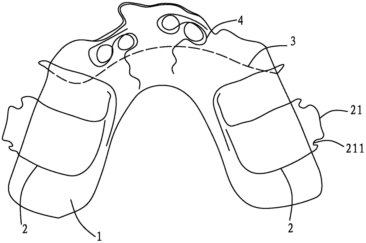
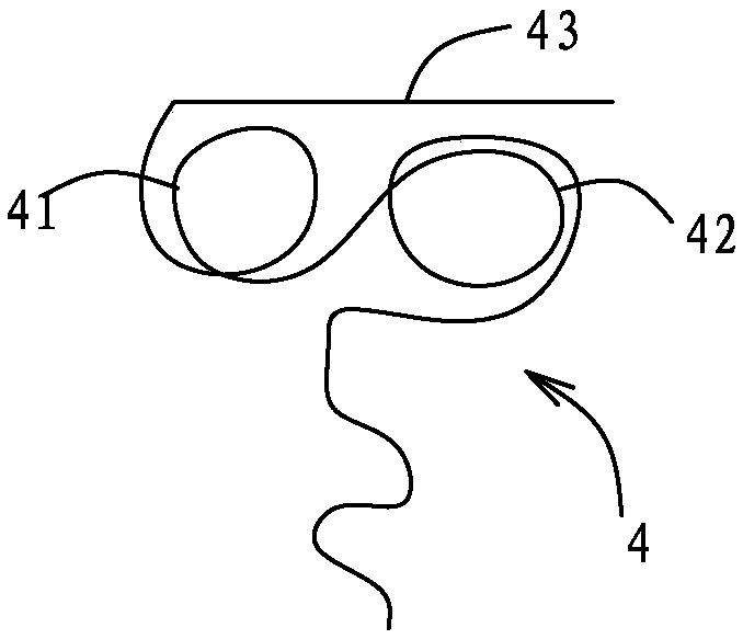
[0014] refer to figure 1 and figure 2 : push spring orthosis, including base 1, retention card 2, lip bow 3 and push spring 4, lip bow 3 is arc-shaped, retention card 2 is set at both ends of lip bow 3, base 1 cover is set on Lip bow 3 and push spring 4 outsides, one end of push spring 4 is fixed with base support 1, and the other end of push spring 4 is provided with first elastic portion 41 and second elastic portion 42, and push spring 4 is a steel wire product, and the first The elastic part 41 and the second elastic part 42 are O-shaped elastic rings with opposite winding directions. Among them, the base 1 is made of resin, which can reduce the foreign body sensation after the base 1 is installed in the oral cavity, and improve the comfort of use; the retention card 2 and the lip bow 3 are both made of steel wire. In actual use, two, three or four pu...


PUM


Abstract

The invention discloses a pushing spring corrector, including a base holder, retention clamps, a labial arch, and a pushing spring. The labial arch is arc. The retention clamps are on two ends of thelabial arch. The base holder is covered on the outer sides of the labial arch and the pushing spring. One end of the pushing spring is fixed with the base holder, and the other end of the pushing spring is provided with a first elastic portion and a second elastic portion. The pushing spring is a steel wire workpiece. The first elastic portion and the second elastic portion are O-shaped elastic rings whose winding directions are opposite. Through arranging the first elastic portion and the second elastic portion on the pushing spring, and the first elastic portion and the second elastic portion are O-shaped elastic rings in opposite winding directions, so thrust of the pushing spring can be greatly improved. Through thrust of the pushing spring, physiological movement of teeth can be resisted or promoted, and teeth move along orthodontic directions. Through the two O-shaped elastic rings, teeth are provided by large thrust all along in a process that the teeth are corrected, so as to achieve required correction effect.

Description

technical field [0001] The invention belongs to a medical device for dental correction, in particular to a push spring correction device. Background technique [0002] In the current technology, orthodontic devices are mainly divided into two categories: fixed and movable, and the devices described here are specifically aimed at the movable category. For fixed orthodontic appliances, the existing ones mainly include "L" type and double "T" push springs. As the teeth are gradually corrected during orthodontics, their thrust gradually decreases, making it impossible to meet the power of orthodontics in the later stage. to achieve the desired orthodontic effect. Contents of the invention [0003] The object of the present invention is to provide a push spring orthotic that can solve at least one of the above-mentioned problems. [0004] According to one aspect of the present invention, a push spring orthotic is provided, including a base, a retention card, a lip bow and a p...

Claims


Application Information

Patent Timeline
Patent Type & Authority Applications(China)
IPC IPC(8): A61F7/00
CPCA61F7/00
Inventor 刘秀兰姜琴尹春肖海花刘书杞
Owner 佛山市佛冠义齿有限公司
Why Eureka
Try Eureka