Fixing mechanism for external circle grinding of sleeve-like mechanical components

A technology of mechanical parts and cylindrical grinding, which is applied in the field of machine parts processing devices, can solve problems such as inconsistent angles, low production efficiency, and different degrees of cylindrical grinding of workpieces, and achieve the effect of improving processing efficiency

Inactive Publication Date: 2017-08-18
绵竹市凯瑞机械加工有限公司
View PDF8 Cites 4 Cited by
  • Summary
  • Abstract
  • Description
  • Claims
  • Application Information

AI Technical Summary

Problems solved by technology

[0002] When processing the sleeve parts in the mechanical workshop, it is necessary to grind the outer circle of the sleeve parts. When performing this process, the technical standard to be followed is that the outer circle and the inner hole of the sleeve parts must be at the same Shaft, that is, when grinding, the outer circle of the sleeve parts should be ground based on the inner hole to achieve the coaxial requirements of the outer circle and the inner hole of the sleeve parts, and the outer circle itself is the left and right sides of the outer circle. The end must also be coaxial. Now the usual practice is to grab one end of the sleeve workpiece to be processed by the three-jaw chuck, and then process the workpiece on the grinding machine. After one end is processed, loosen the workpiece by the three-jaw chuck and then grab The other end of the workpiece is processed. Due to the clamping error of the three-jaw chuck, the angles of clamping the workpiece twice before and after cannot be guaranteed to be consistent. Therefore, it is easy to cause different degrees of grinding of the outer circle of the workpiece twice before and after, which affects Subsequent installation and use, and when processing sleeve workpieces, the three-jaw chuck can only clamp one workpiece at a time, and cannot process multiple sleeve workpieces at the same time, so the production efficiency is low

Method used


Image

  • Fixing mechanism for external circle grinding of sleeve-like mechanical components
  • Fixing mechanism for external circle grinding of sleeve-like mechanical components
  • Fixing mechanism for external circle grinding of sleeve-like mechanical components

Examples


Embodiment

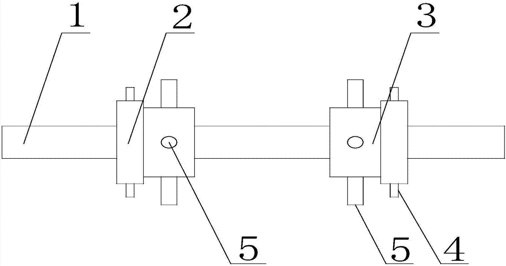
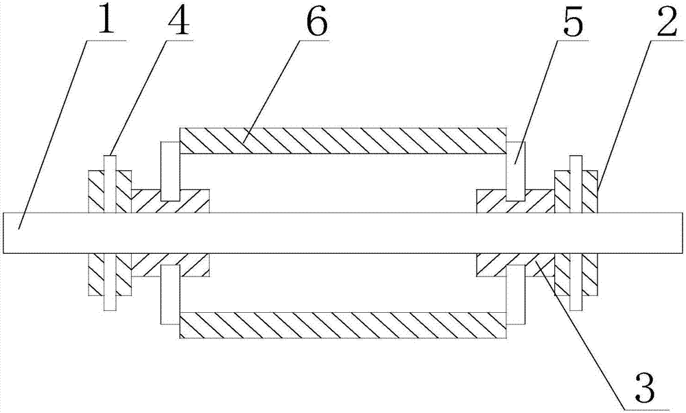
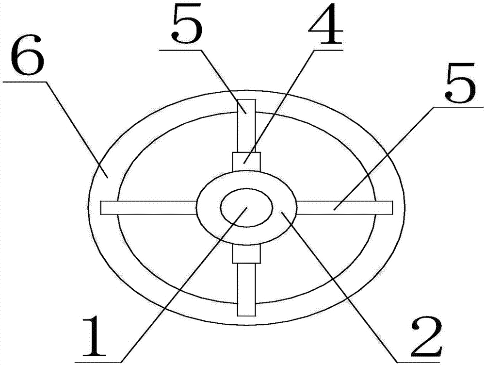
[0022] Such as Figure 1 to Figure 3 As shown, the fixing mechanism for the cylindrical grinding of sleeve mechanical parts of the present invention includes a shaft 1, which can be clamped by a three-jaw chuck, and the shaft 1 is provided with two clamping blocks 3, two The clamping blocks 3 are all hollow cylindrical shapes, that is, the two bottom surfaces of the clamping block 3 are provided with circular holes, and the circular holes on the two bottom surfaces communicate with each other, the clamping blocks 3 are sleeved on the shaft rod 1, and can Freely move on the shaft 1 to adjust the distance between the two clamping blocks 3 to meet the clamping of sleeve workpieces 6 of different lengths. The circumferential surface of the clamping block 3 is provided with four blind Holes, four blind holes are evenly distributed on the circumferential surface of the clamping block 3, a baffle 5 is arranged in the four blind holes, the baffle 5 is connected with the blind hole on ...


PUM


Abstract

The invention discloses a fixing mechanism for cylindrical grinding of sleeve mechanical parts, which includes a shaft rod, a positioning block and a clamping block are arranged on the shaft rod, two adjusting rods are arranged on the positioning block, and the adjusting rod connects with the positioning block through a screw thread. Connection, used to fix the positioning block on the shaft rod, there are several baffles on the clamping block, the baffles are connected with the clamping block through threads, and the baffles are used to block the side of the sleeve parts between the two clamping blocks The height of the baffle can be adjusted by rotating the baffle to meet the clamping of sleeve parts with different diameters. The invention is simple in structure, easy to operate, can ensure that the outer circle of the sleeve workpiece is coaxial with the shaft, improves the cutting accuracy, and can hold multiple sleeve workpieces at the same time, satisfying the simultaneous processing of multiple sleeve workpieces, and improving the accuracy of sleeve workpieces. production efficiency.

Description

technical field [0001] The invention relates to a machining device for machine parts, in particular to a fixing mechanism for cylindrical grinding of sleeve-type mechanical parts. Background technique [0002] When processing the sleeve parts in the mechanical workshop, it is necessary to grind the outer circle of the sleeve parts. When performing this process, the technical standard to be followed is that the outer circle and the inner hole of the sleeve parts must be at the same Shaft, that is, when grinding, the outer circle of the sleeve parts should be ground based on the inner hole to achieve the coaxial requirements of the outer circle and the inner hole of the sleeve parts, and the outer circle itself is the left and right sides of the outer circle. The end must also be coaxial. Now the usual practice is to grab one end of the sleeve workpiece to be processed by the three-jaw chuck, and then process the workpiece on the grinding machine. After one end is processed, l...

Claims


Application Information

Patent Timeline
Patent Type & Authority Applications(China)
IPC IPC(8): B24B5/35B24B5/04B24B41/06
CPCB24B5/35B24B5/04B24B41/06
Inventor 宋传斌
Owner 绵竹市凯瑞机械加工有限公司
Why Eureka
Try Eureka