A manual adjustment system for arbitrary spacing of saw blades for cutting plates of different thicknesses

A manual adjustment and saw blade technology, which is applied in the direction of sawing machine, metal sawing equipment, metal processing equipment, etc., can solve the problems of lower adjustment efficiency, complex adjustment structure, inability to adjust the saw blades at any distance, and achieve adjustment efficiency High, easy-to-operate effect

Active Publication Date: 2019-07-02
MIANYANG FEIYUAN TECH CO LTD
View PDF5 Cites 0 Cited by
  • Summary
  • Abstract
  • Description
  • Claims
  • Application Information

AI Technical Summary

Problems solved by technology

[0004] The purpose of the present invention is to overcome the deficiencies of the prior art and provide a manual adjustment system for the arbitrary spacing of the saw blades for cutting plates of different thicknesses. Complicated, and it is impossible to adjust the arbitrary spacing of the saw blades of different thickness plates at the same time
[0005] In addition, when the existing multi-blade band saw device needs to be adjusted, the motor driving the saw blade must be stopped to adjust the distance between each saw blade, thereby reducing the adjustment efficiency. In addition, the adjustment of the saw blade can only be done once. The adjustment of one sheet cannot realize the synchronization of any number of saw blades

Method used


Image

  • A manual adjustment system for arbitrary spacing of saw blades for cutting plates of different thicknesses
  • A manual adjustment system for arbitrary spacing of saw blades for cutting plates of different thicknesses
  • A manual adjustment system for arbitrary spacing of saw blades for cutting plates of different thicknesses

Examples


Embodiment

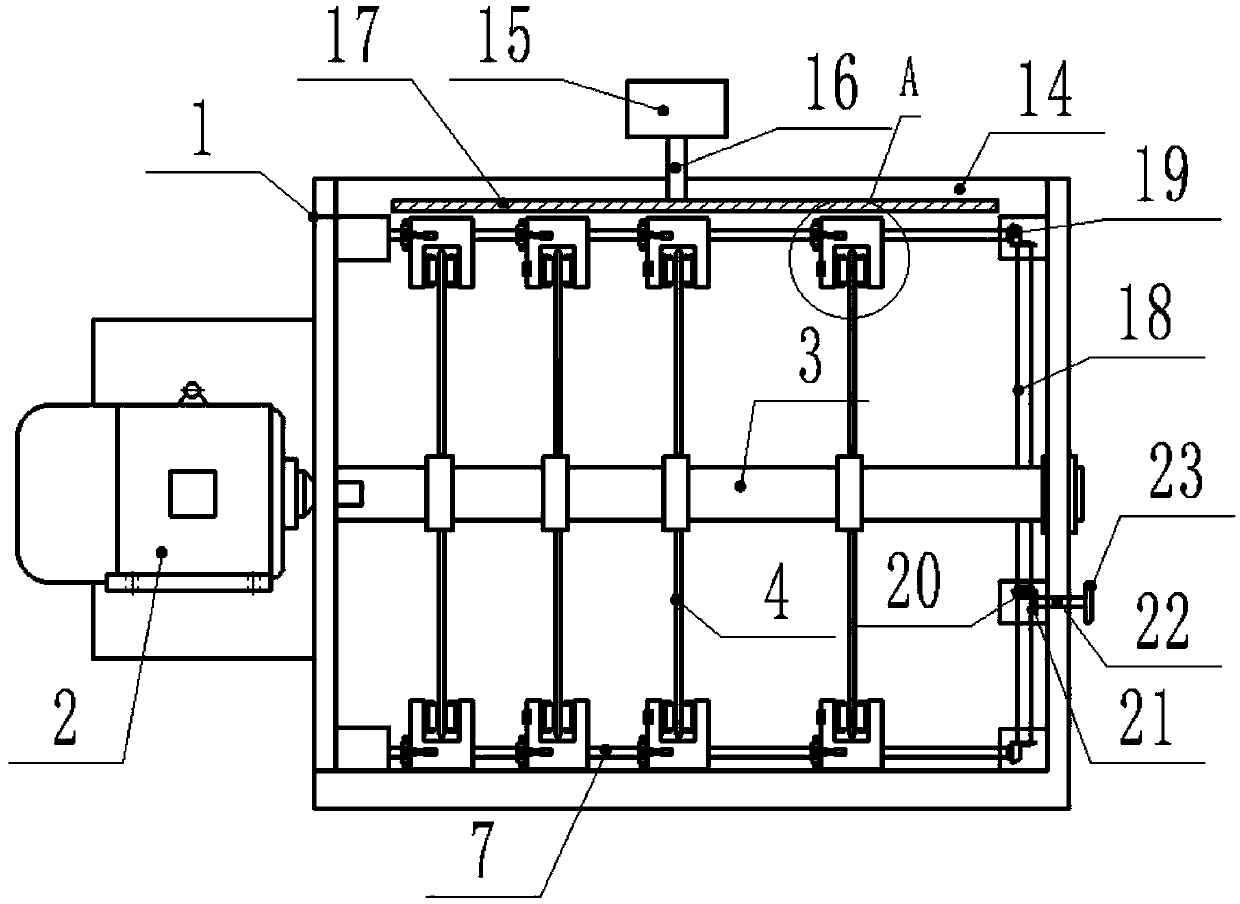
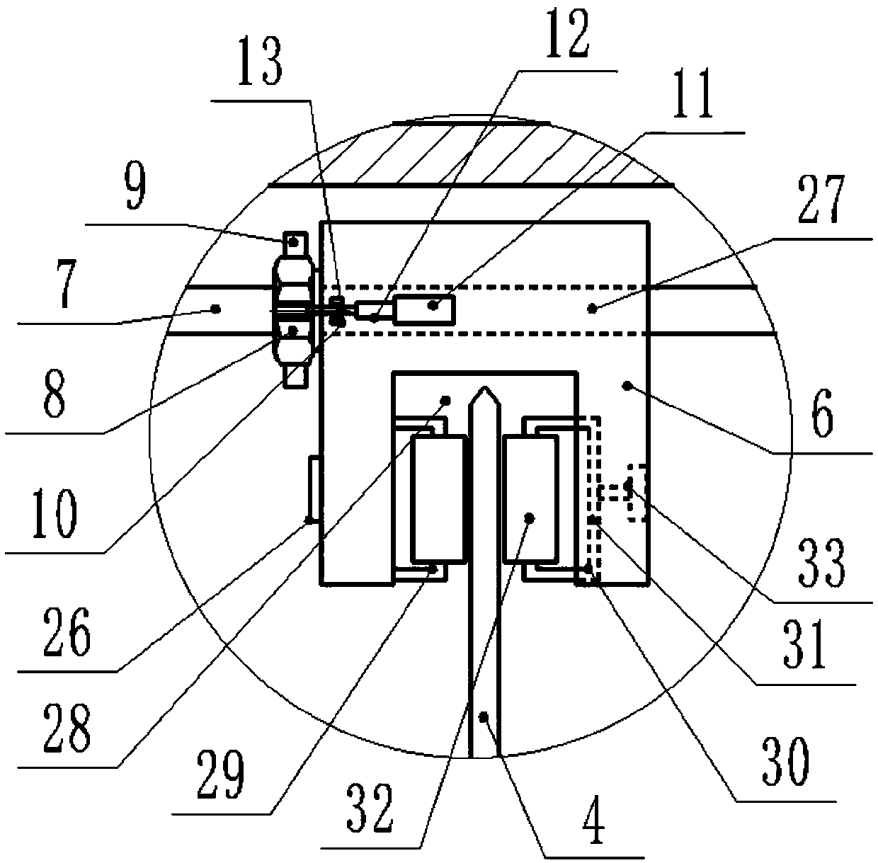
[0032] Such as Figure 1-3 As shown, the present invention 1. A manual adjustment system for the arbitrary pitch of saw blades for cutting plates of different thicknesses, comprising an electric saw support frame 1, a motor 2, a saw blade spline shaft 3, and a saw blade 4. The electric saw support frame 1 There is a saw blade spline shaft 3 in the middle. The multiple saw blades 4 are sleeved on the saw blade spline shaft 3 through a spline sleeve. The spline sleeve and the saw blade spline shaft 3 cooperate with each other and rotate on the saw blade spline shaft 3 At the same time, the saw blade 4 can be driven to rotate synchronously. At the same time, after contacting the left and right movement limits of the saw blade, the saw blade 4 can move on the saw blade spline shaft 3, and the motor 2 is connected to the saw blade spline shaft 3. At one end, the motor 2 drives the saw blade spline shaft 3 and the saw blade 4 on the saw blade spline shaft 3 to work. A saw blade adjus...


PUM


Abstract

The invention discloses a manual adjusting system for any distance between saw blades for cutting plates of different thicknesses. A saw blade spline rotating shaft is arranged in the middle of an electric saw supporting frame. The multiple saw blades are arranged on the saw blade spline rotating shaft through spline sleeves in a sleeving manner. A motor is connected to one end of the saw blade spline rotating shaft. The saw blade spline rotating shaft and the saw blades on the saw blade spline rotating shaft are driven through the motor to work. Saw blade adjusting clamp blocks are arranged on the two sides of each saw blade, the saw blade adjusting clamp blocks on one corresponding sides of all the saw blades are arranged on a lead screw in a sleeving manner, and the two lead screws arecorrespondingly mounted on the two sides of the electric saw supporting frame. An adjusting nut is arranged at the position, on one side of each saw blade adjusting clamp block, of the corresponding lead screw. A nut limiting clamp groove is arranged on each adjusting nut in a surrounding manner. Clamp block limiting clamp grooves corresponding to the nut limiting clamp grooves are arranged on thesaw blade adjusting clamp blocks. A set of air cylinder is arranged on each saw blade adjusting clamp block, a pin block is arranged on a telescopic arm of each air cylinder, and the nut limiting clamp grooves and the clamp block limiting clamp grooves are in pinned connection by controlling the pin blocks through the air cylinders.

Description

Technical field [0001] The invention relates to the field of furniture processing equipment, in particular to a system for manually adjusting the arbitrary spacing of saw blades for cutting plates of different thicknesses. Background technique [0002] The existing multi-piece band saw device can cut multiple strips at one time, improve the cutting efficiency and reduce material loss. For processing slats or boards of different thicknesses, it is necessary to adjust the distance between any two saw blades. The prior art discloses that the distance between all saw blades can be adjusted to the same size at the same time, but the adjustment structure is more complicated, and for simultaneous sawing The arbitrary spacing of saw blades of different thickness plates cannot be adjusted. [0003] In addition, when the existing multi-blade band saw device needs to be adjusted, the motor driving the saw blade must be stopped to adjust the distance between the saw blades, thereby reducing t...

Claims


Application Information

Patent Timeline
Patent Type & Authority Patents(China)
IPC IPC(8): B23D47/00B23D45/10
CPCB23D45/10B23D47/00
Inventor 李艳芬
Owner MIANYANG FEIYUAN TECH CO LTD
Why Eureka
Try Eureka