Roller type jacking excavator

A kind of excavator and drum-type technology, which is applied in the field of drum-type jacking excavators. It can solve the problems of poor soil-breaking ability of pipe jacking machines, manual transportation of earthwork, and slow excavation speed, so as to achieve high jacking operation efficiency and excavation. The effect of fast soil speed and enhanced soil breaking ability

Inactive Publication Date: 2017-08-18
成都市德容建筑劳务有限公司
View PDF0 Cites 3 Cited by
  • Summary
  • Abstract
  • Description
  • Claims
  • Application Information

AI Technical Summary

Problems solved by technology

[0004] In order to solve the problems of poor soil-breaking ability, slow digging speed and manual transportation of earthwork in existing pipe jacking machines, the purpose of the present invention is to provide a drum-type jacking excavator

Method used


Image

  • Roller type jacking excavator
  • Roller type jacking excavator

Examples


Embodiment 1

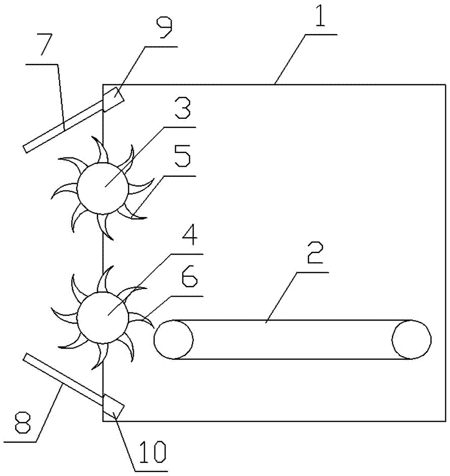
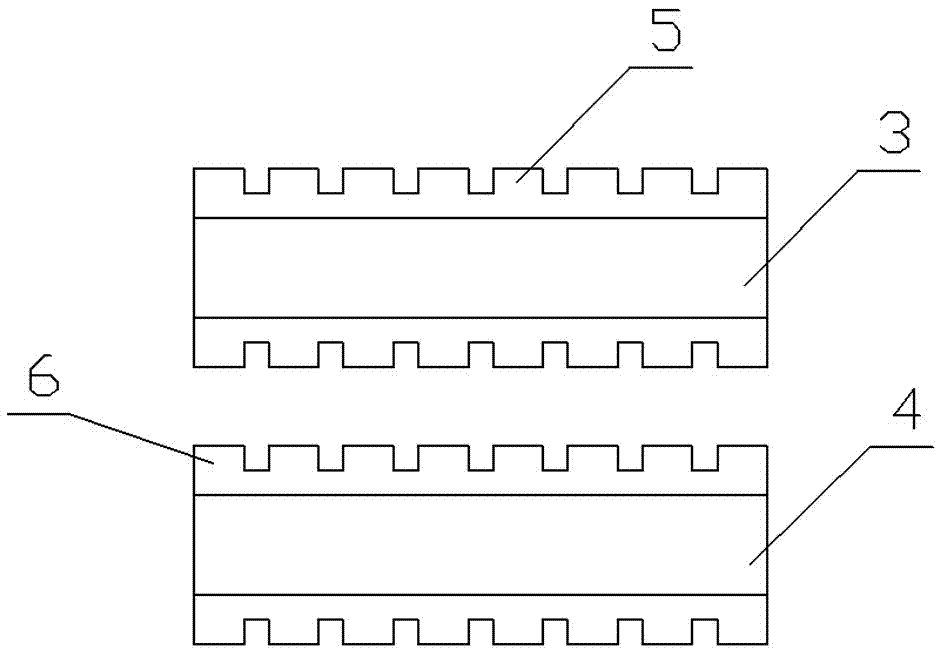
[0023] Such as figure 1 and figure 2 As shown, it includes a cylinder body 1, a roller group arranged on the front panel of the cylinder body 1, and a soil conveyor belt 2 fixed in the cylinder body 1; the roller group includes an upper roller 3 and a lower roller arranged up and down in the vertical direction 4. The two ends of the rotating shafts of the upper drum 3 and the lower drum 4 are respectively connected to the left and right side walls of the cylinder 1 in rotation; the upper drum 3 is provided with evenly distributed upper scrapers 5, and the lower drum 4 is provided with evenly distributed lower scrapers 6 , There is a gap between the upper scraper 5 and the lower scraper 6;

[0024] The rotation direction of the upper drum 3 is opposite to that of the lower drum 4; outside the cylinder body 1, the upper drum 3 rotates from top to bottom, and the lower drum 4 rotates from bottom to top.

[0025] The edge of the upper scraper 5 is bent in the direction of rotat...

Embodiment 2

[0030] Such as figure 1 and figure 2 As shown, it includes a cylinder body 1, a roller group arranged on the front panel of the cylinder body 1, and a soil conveyor belt 2 fixed in the cylinder body 1; the roller group includes an upper roller 3 and a lower roller arranged up and down in the vertical direction 4. The two ends of the rotating shafts of the upper drum 3 and the lower drum 4 are respectively connected to the left and right side walls of the cylinder 1 in rotation; the upper drum 3 is provided with evenly distributed upper scrapers 5, and the lower drum 4 is provided with evenly distributed lower scrapers 6 , There is a gap between the upper scraper 5 and the lower scraper 6;

[0031] The rotation direction of the upper drum 3 is opposite to that of the lower drum 4; outside the cylinder body 1, the upper drum 3 rotates from top to bottom, and the lower drum 4 rotates from bottom to top.

[0032] The edge of the upper scraper 5 is bent in the direction of rotat...

Embodiment 3

[0036] Such as figure 1 and figure 2 As shown, it includes a cylinder body 1, a roller group arranged on the front panel of the cylinder body 1, and a soil conveyor belt 2 fixed in the cylinder body 1; the roller group includes an upper roller 3 and a lower roller arranged up and down in the vertical direction 4. The two ends of the rotating shafts of the upper drum 3 and the lower drum 4 are respectively connected to the left and right side walls of the cylinder 1 in rotation; the upper drum 3 is provided with evenly distributed upper scrapers 5, and the lower drum 4 is provided with evenly distributed lower scrapers 6 , There is a gap between the upper scraper 5 and the lower scraper 6;

[0037] The rotation direction of the upper drum 3 is opposite to that of the lower drum 4; outside the cylinder body 1, the upper drum 3 rotates from top to bottom, and the lower drum 4 rotates from bottom to top.

[0038] The edge of the upper scraper 5 is bent in the direction of rotat...


PUM


Abstract

The invention discloses a drum-type jacking excavator, which comprises a cylinder body, a cylinder group arranged on the front panel of the cylinder body, and a soil conveyor belt fixed in the cylinder body; The upper roller and the lower roller, the two ends of the rotating shafts of the upper roller and the lower roller are respectively connected to the left and right side walls of the cylinder; the surface of the upper roller is equipped with evenly distributed upper scrapers, and the surface of the lower roller is equipped with evenly distributed lower scrapers and upper scrapers. There is a gap between the scraper and the lower scraper; the soil conveyor belt is set close to the junction of the upper scraper and the lower scraper. The beneficial effects of the invention are: through the cooperation of the drill and the scraper, the soil-breaking ability is greatly strengthened, the excavation speed is fast, the jacking operation efficiency is high, the degree of automation is high, and the amount of manual labor is reduced.

Description

technical field [0001] The invention belongs to the technical field of pipe jacking engineering equipment, and in particular relates to a drum-type jacking excavator. Background technique [0002] Pipe jacking construction is a non-excavation construction method, and it is a pipeline burying construction technology that does not excavate or excavates less. The pipe jacking method is to use the jacking equipment in the working pit to overcome the friction between the pipe and the surrounding soil, push the pipe into the soil, and excavate the earth and transport it away. After one section of pipe is pushed into the soil layer, the second section of pipe is added to continue jacking. Its principle is to push the tool pipe or pipe jacking machine from the working pit through the soil layer to the receiving pit by means of the thrust of the main jacking cylinder, the pipe room, and the relay room. The pipeline is buried between the two pits immediately after the tool pipe or t...

Claims


Application Information

Patent Timeline
Patent Type & Authority Applications(China)
IPC IPC(8): E21D9/10E21D9/12
CPCE21D9/1006E21D9/12
Inventor 曾晓予
Owner 成都市德容建筑劳务有限公司
Why Eureka
Try Eureka