
Improved engine oil cooling module shell

An oil cooling and housing technology, applied in mechanical equipment, engine components, engine lubrication, etc., can solve the problems of rotor impact, oil absorption difficulty, easy to produce cavitation, etc., to reduce hedging, avoid oil absorption difficulty, and reduce the influence of eddy current. Effect

Active Publication Date: 2017-08-18
HUNAN JIALI MACHINERY
View PDF5 Cites 2 Cited by
  • Summary
  • Abstract
  • Description
  • Claims
  • Application Information

AI Technical Summary

Problems solved by technology

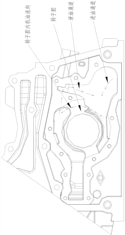
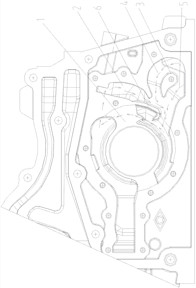
However, due to the structural limitation of the oil cooling module, in order to save space, the distance between the oil drain channel and the rotor cavity is usually relatively close, and the high-pressure oil in the oil drain channel often directly enters the rotor cavity without being fully mixed with the low-pressure oil in the inlet channel, causing damage to the rotor. At the same time, because the flow direction of the high-pressure oil in the oil discharge channel is opposite to the flow direction of the oil in the rotor cavity, the two oils will produce strong hedging, and a large eddy current will be generated in the rotor cavity, which will not only easily cause cavitation, but also easily lead to Difficulty absorbing oil

Method used


Image

  • Improved engine oil cooling module shell
  • Improved engine oil cooling module shell

Examples


Embodiment Construction

[0017] In order to facilitate the understanding of those skilled in the art, the present invention will be further described below with reference to the embodiments and the accompanying drawings, and the contents mentioned in the embodiments are not intended to limit the present invention.

[0018] In the description of the present invention, it should be understood that the terms "center", "longitudinal", "lateral", "length", "width", "thickness", "upper", "lower", "front", " rear, left, right, vertical, horizontal, top, bottom, inside, outside, clockwise, counterclockwise, etc., or The positional relationship is based on the orientation or positional relationship shown in the accompanying drawings, which is only for the convenience of describing the present invention and simplifying the description, rather than indicating or implying that the referred device or element must have a specific orientation, be constructed and operated in a specific orientation, Therefore, it shou...


PUM


Abstract

The invention discloses an improved engine oil cooling module shell which is provided with an engine oil pump rotor cavity, an oil drainage channel and an oil inlet channel. An extending oil blocking separation plate is arranged on the side, close to the rotor cavity, of the outlet end of the oil drainage channel and is in a J shape, and the bending direction of the tail of the oil blocking separation plate is consistent with the flowing direction of engine oil in the rotor cavity. Through the structure, high-pressure oil in the oil drainage channel is blocked by the oil blocking separation plate and prevented from directly entering the rotor cavity, and the high-pressure oil must be fully mixed with inlet oil at the lower side and then enters the rotor cavity, so that impact of the high-pressure oil to a rotor is lowered; meanwhile, the lower end of the oil blocking separation plate is of a bent structure with the direction being approximate to the flowing direction of the oil in the rotor cavity, so that the oil inlet direction is guided to be consistent with the flowing direction of the oil in the rotor cavity, counter-impact is reduced, and the cavitation risk is lowered.

Description

technical field [0001] The present invention relates to an improved oil cooling module housing. Background technique [0002] The pressure relief method of the oil pump outlet in the traditional oil cooling module usually adopts the internal relief type, that is, when the outlet pressure of the oil pump exceeds the opening pressure of the pressure limiting valve, the pressure limiting valve is opened, and the oil pump outlet is communicated with the oil inlet channel through the oil drain channel. , the high pressure oil returns to the oil inlet channel through the oil drain channel, and the high pressure oil and the low pressure oil enter the rotor cavity together after being fully mixed (see figure 1 ). However, due to the structural limitation of the oil cooling module, in order to save space, the distance between the oil drain channel and the rotor cavity is usually close, and the high-pressure oil in the oil drain channel often enters the rotor cavity directly without ...

Claims


Application Information

Patent Timeline
Patent Type & Authority Applications(China)
IPC IPC(8): F16N13/20F16N39/02
CPCF16N13/20F16N39/02
Inventor 许仲秋魏彪刘光明阳波
Owner HUNAN JIALI MACHINERY
Learn More