Fin stabilizer, covering element and water vehicle

A stabilizer, cover element technology, used in the field of fin stabilizers, cover elements and boats

Inactive Publication Date: 2017-08-18
斯凯孚海运有限公司
View PDF8 Cites 4 Cited by
  • Summary
  • Abstract
  • Description
  • Claims
  • Application Information

AI Technical Summary

Problems solved by technology

Although the use of the empennage as a cover element does not require additional cover elements or drivers, however, with extended stabilizer fins it is not possible to at least partially cover the opening

Method used


Image

  • Fin stabilizer, covering element and water vehicle
  • Fin stabilizer, covering element and water vehicle
  • Fin stabilizer, covering element and water vehicle

Examples


Embodiment Construction

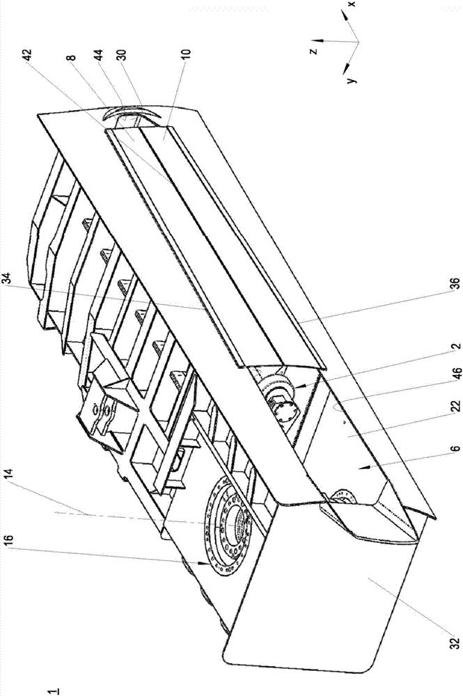
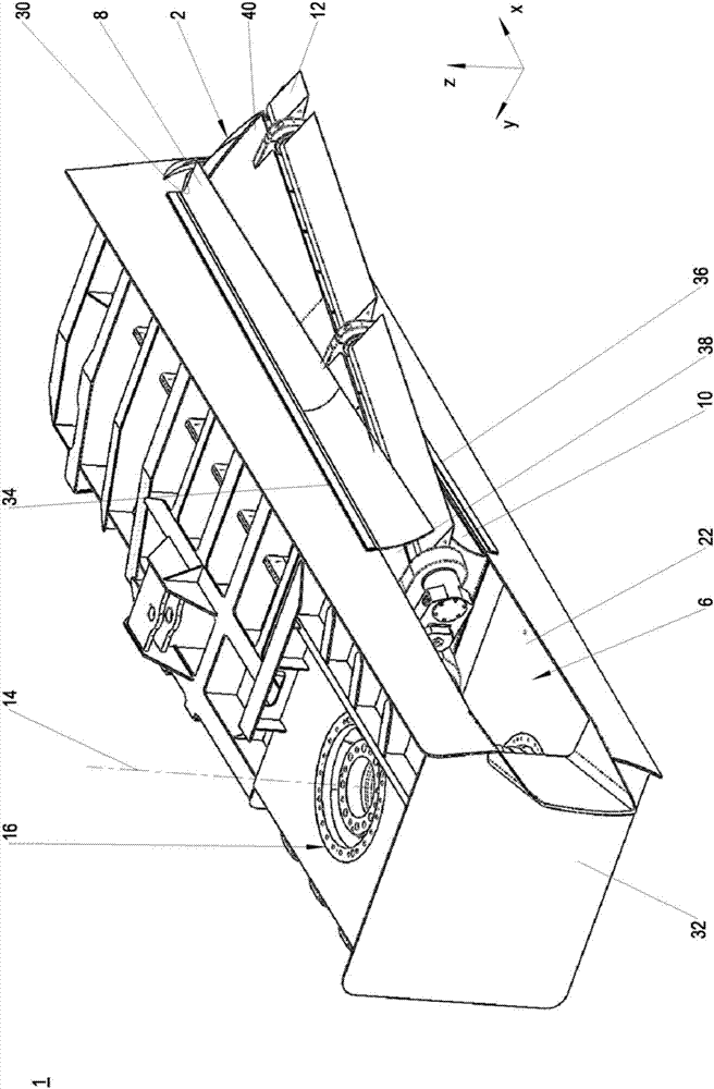
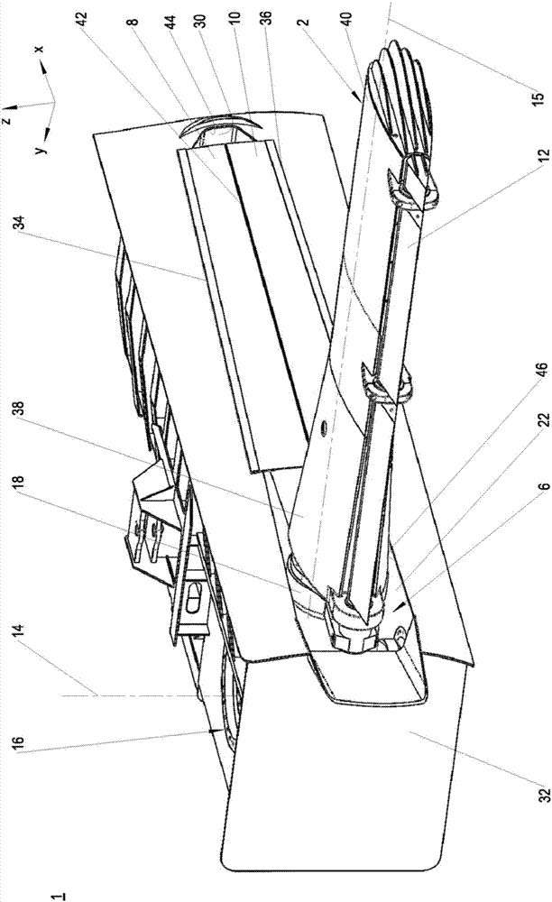
[0044] exist Figure 1 to Figure 3 In , different operating states of a first exemplary embodiment of a fin stabilizer 1 of the invention for stabilizing a watercraft, in particular a boat, are shown. Usually, at least one fin stabilizer 1 is arranged laterally on the underwater vessel, respectively. Although figure 1 Fin stabilizer 1 in is shown with retracted stabilizer fin 2, but in figure 2 is shown with extended stabilizer fins 2, and in image 3 is shown with extended stabilizer fins.

[0045] In addition to the stabilizer fin 2, the fin stabilizer 1 has a substantially not shown drive for pivoting the stabilizer fin 2, a receiving space 6 for receiving the retracted stabilizer fin 2 and two open side covers Elements 8, 10. under the Figures 1 to 16 All exemplary embodiments two to nine described in include the same aforementioned features: pivotable stabilizer fin 2 , driver and receiving space 6 . Variations exist only for cover elements or cover elements 8, 1...


PUM


Abstract

The invention relates to a fin stabilizer (1) for stabilizing water vehicles, comprising a pivotable stabilizing fin (2), a fin box (6) for receiving the stabilizer fin in the pivoted state, and at least one covering element (8) for at least partially covering a fin box opening, through which the stabilizer fin exits and enters the fin box during swiveling in and out, wherein the at least one covering element (8) is resilient. The invention also relates to a covering element for a fin box opening and a water vehicle having at least one fin stabilizer.

Description

technical field [0001] The invention relates to a fin stabilizer for stabilizing a watercraft, a cover element and a watercraft according to the preamble of claim 1 . Background technique [0002] Fin stabilizers are used to dampen the rolling motion of a boat or boat. In principle there are two types of fin stabilizers. A fin stabilizer including a stabilizer fin retractable into the hull and a fin stabilizer including a non-retractable stabilizer fin. The present invention relates to fin stabilizers comprising retractable stabilizer fins. For this purpose, the fin stabilizer has a receiving space or fin box, which is introduced into the hull and opens out to the water side through openings. The fin box is sealed relative to the hull interior. During retraction and extension, the stabilizer fins enter or exit through openings in the fin box. This opening is slightly larger than the cross section of the stabilizer fin. In operation, water is forced or sucked into the f...

Claims


Application Information

Patent Timeline
Patent Type & Authority Applications(China)
IPC IPC(8): B63B39/06
CPCB63B39/06B63B2039/068
Inventor F.阿尔布雷希特U.阿尔布雷希特K.丹内贝格T.西布雷希特H.斯帕德尔M.佐伦科普夫U.莱特洛夫
Owner 斯凯孚海运有限公司
Why Eureka
Try Eureka