Rotary Ring Soil Trough Test Bench Drive Mechanism

A technology of annular soil trough and drive mechanism, which is applied in the testing of transmission devices, mechanical equipment, and mechanical components, etc., can solve the problems of inconsistency, inaccurate rotation speed of annular soil trough, and decrease in the quality of detection and test, and achieve reliable driving engagement and transmission. The effect of high precision and novel structure

Active Publication Date: 2019-03-05
HEILONGJIANG PROV AGRI MACHINERY ENG SCI INST +1
View PDF5 Cites 3 Cited by
  • Summary
  • Abstract
  • Description
  • Claims
  • Application Information

AI Technical Summary

Problems solved by technology

However, since the existing rotary ring-shaped soil tank drive structure uses the friction between the driving rubber wheel and the rubber ring to drive the ring-shaped soil tank to generate rotational motion, it is found in the practice of scientific research and experiments that the friction between the rubber wheel and the rubber ring often Slipping occurs due to force changes, resulting in inaccurate and inconsistent rotational speed of the annular soil tank, which affects the accuracy and reliability of the test data of test components such as seed metering devices, and the quality of the test is degraded, making it impossible to make accurate evaluations of the tested components

Method used


Image

  • Rotary Ring Soil Trough Test Bench Drive Mechanism
  • Rotary Ring Soil Trough Test Bench Drive Mechanism
  • Rotary Ring Soil Trough Test Bench Drive Mechanism

Examples


Embodiment Construction

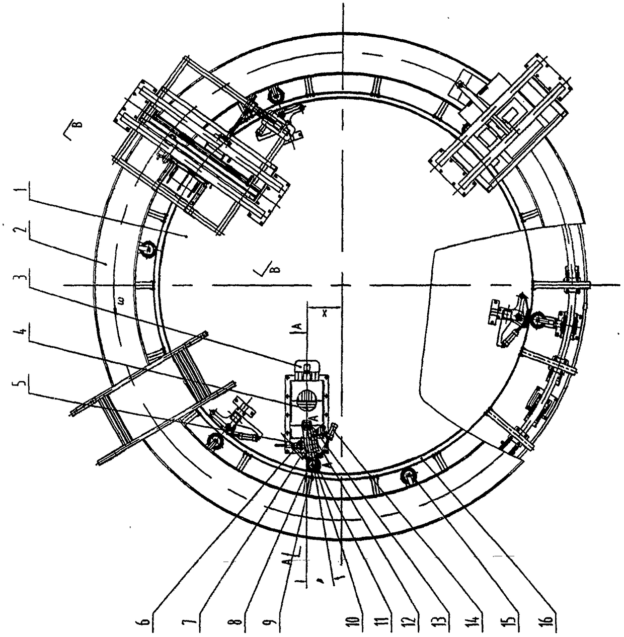
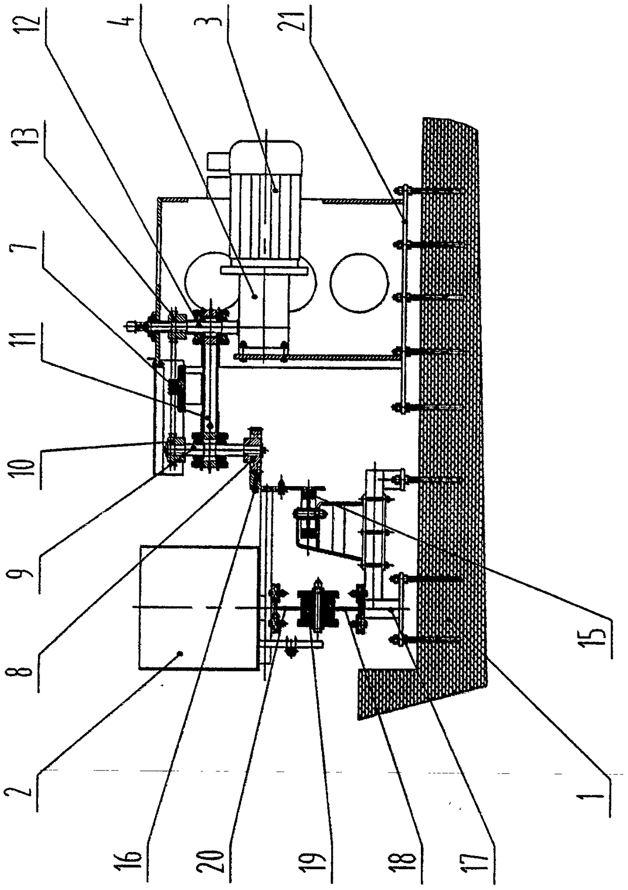
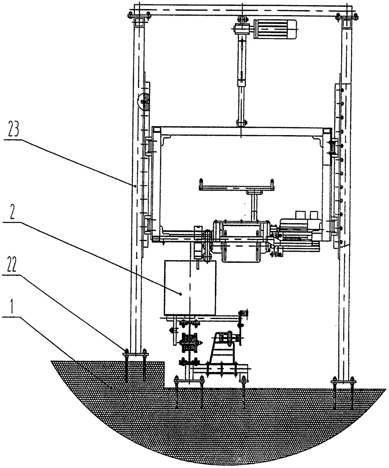
[0011] Embodiments of the present invention will be described in detail below in conjunction with the accompanying drawings. A rotary annular soil tank test bench drive mechanism, a circular track support 17 is fixed on the outer edge of the base 1, and an annular lower track 18 with soil tank rollers 19 is fixed on the circular track support 17, The ring-shaped soil tank 2 is fixed on the ring-shaped upper track 20, the soil tank roller 19 is arranged on the position between the ring-shaped upper and lower tracks 20, 18, and the ring-shaped soil tank 2 is rotatably supported and installed on the ring-shaped lower track by the soil tank roller 19 18, the combined ring gear 16 is fixed on the annular inner part of the annular soil tank 2, and a plurality of center positioning rollers 15 are evenly distributed along the circumferential direction on the annular track support 17, and the center positioning The roller 15 is in contact with the cylindrical outer wall of the combined...


PUM


Abstract

The invention discloses a drive mechanism for a rotary annular soil bin test bed, and belongs to scientific research test equipment. A combined inner gear ring is fixedly installed on an annular soil bin; a plurality of central location wheels are assembled on an annular rail support; a drive mechanism support is installed on a base; a variable-frequency and variable-speed motor and a reversing transmission are installed on the drive mechanism support; a rotary seat is installed on a power output shaft of the reversing transmission in a sleeving manner; a drive chain wheel is fixedly installed on the power output shaft; a drive shaft is assembled on the rotary seat; a drive gear and a driven chain wheel are fixedly installed on the drive shaft; a chain is assembled on the drive chain wheel and the driven chain wheel in a sleeving manner; a tensioning chain wheel is assembled on the rotary seat; a return tension spring is connected to the rotary seat and the drive mechanism support; and a drive cylinder is connected to the drive mechanism support and the rotary seat. The mechanism is novel and reasonable in structure, reliable in drive and engagement, high in transmission accuracy, and stable in running, and ensures the test detection accuracy of a working component of an agricultural implement.

Description

technical field [0001] The invention belongs to scientific research and test equipment, and mainly relates to a rotary annular soil tank driving mechanism used in the test of agricultural machinery operation parts. Background technique [0002] Based on many characteristics such as small footprint, compact equipment, high test efficiency, low manufacturing cost, and wide application range, the rotary annular soil tank test equipment has been widely used in agricultural machinery research institutes, which is a great contribution to the improvement of scientific and technological level, Accelerating the maturity of scientific and technological achievements has played a positive role. However, since the existing rotary ring-shaped soil tank drive structure uses the friction between the driving rubber wheel and the rubber ring to drive the ring-shaped soil tank to generate rotational motion, it is found in the practice of scientific research and experiments that the friction be...

Claims


Application Information

Patent Timeline
Patent Type & Authority Patents(China)
IPC IPC(8): F16H37/02G01M13/00
CPCF16H37/02G01M13/00
Inventor 马君张文毅刘俊杰袁文胜孙先明胡敏娟杨存志赵德春余涛
Owner HEILONGJIANG PROV AGRI MACHINERY ENG SCI INST
Why Eureka
Try Eureka