
A method and system for synchronizing multiple CCD cameras

A camera and image technology, which is applied in the field of computer images, can solve the problems of rapid and severe changes in unapplicable forms, achieve high synchronization accuracy and reduce costs

Active Publication Date: 2019-07-12
INST OF COMPUTING TECH CHINESE ACAD OF SCI
View PDF5 Cites 0 Cited by
  • Summary
  • Abstract
  • Description
  • Claims
  • Application Information

AI Technical Summary

Problems solved by technology

However, this method is not suitable for situations where the shape of the object being photographed changes rapidly and drastically.

Method used


Image

  • A method and system for synchronizing multiple CCD cameras
  • A method and system for synchronizing multiple CCD cameras
  • A method and system for synchronizing multiple CCD cameras

Examples


Embodiment Construction

[0047] The present invention will be described in detail below in conjunction with the accompanying drawings and specific embodiments.

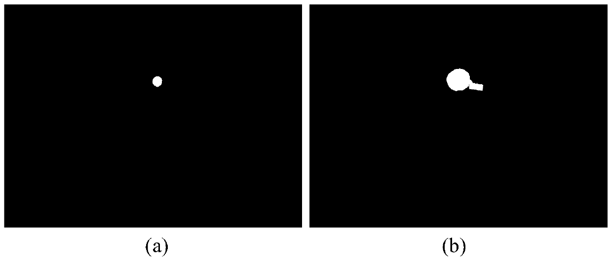
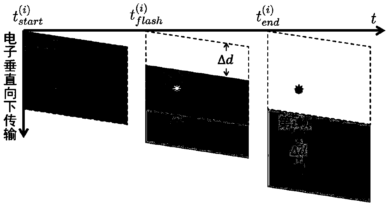
[0048] The inventor found through research that the smear phenomenon of a charge-coupled device (CCD) can be used to realize the synchronization of multiple CCD cameras.

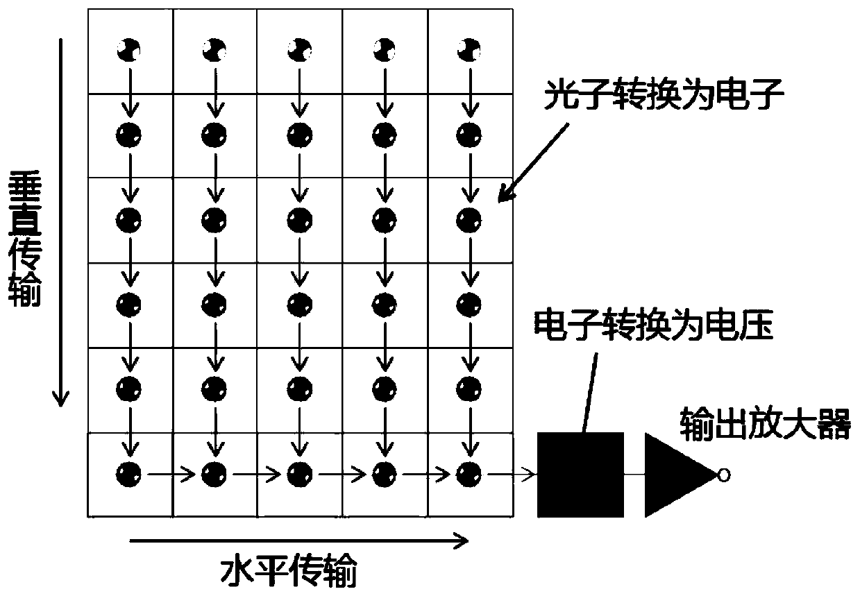
[0049] The CCD is a semiconductor device for imaging, figure 1 The imaging process of the CCD imaging sensor in the CCD camera is shown. refer to figure 1 , when performing imaging, the semiconductor material is first used for photosensitization, the collected photons are converted into charges, and the generated electrons are transported vertically downward line by line (that is, layer by layer). When the electrons are transferred to the registers in the bottom row of the CCD imaging sensor, the electrons are transferred horizontally, and the electrons are converted into voltages to obtain digital information through the output amplifier. After the elements in all rows ...


PUM


Abstract

The invention provides a method for synchronizing multiple CCD cameras, comprising: 1) adjusting the frame rate of each CCD camera to be consistent with the frequency of the stroboscope; 3) adjust the shutter speed of the CCD camera according to the distance between the position of the light source and the position of the smear bright spots in the stroboscope images captured by each of the CCD cameras.

Description

technical field [0001] The invention relates to the field of computer images, in particular to synchronizing cameras in multi-eye vision data collection. Background technique [0002] With the development of hardware technology, cameras are widely used in data acquisition. In recent years, camera-based multi-eye vision data acquisition has become a research hotspot in the fields of computer graphics and computer images. Multi-eye vision refers to shooting the same object from different angles through multiple cameras, so as to use the collected data for visual measurement, three-dimensional reconstruction and other work. [0003] The realization of multi-eye vision is based on the synchronization between each camera, especially when shooting high-speed moving or fast-changing objects, such as shooting flames, it is necessary to ensure a high synchronization between each camera. In the case of large differences in the time of video image data captured by various cameras, it...

Claims


Application Information

Patent Timeline
Patent Type & Authority Patents(China)
IPC IPC(8): H04N5/235H04N5/359H04N5/378
CPCH04N23/73H04N25/626H04N25/75
Inventor 朱登明沈亮王兆其
Owner INST OF COMPUTING TECH CHINESE ACAD OF SCI
Learn More