Valve

A valve seat and valve mechanism technology, applied in the valve field, can solve the problems of large structural space and solenoid valve weight.

Pending Publication Date: 2021-06-04
EBERSPACHER CLIMATE CONTROL SYST GMBH
View PDF8 Cites 0 Cited by
  • Summary
  • Abstract
  • Description
  • Claims
  • Application Information

AI Technical Summary

Problems solved by technology

Such solenoid valves are relatively heavy and require a relatively large ins

Method used


Image

  • Valve
  • Valve
  • Valve

Examples


Embodiment Construction

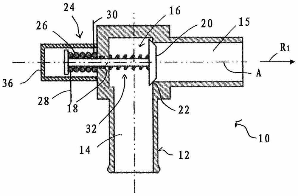
[0026] figure 1 A sectional view of a valve 10 is shown, which can be used, for example, in a heat transfer medium flow circuit in a vehicle for the targeted conduction of a liquid heat transfer medium, for example coolant for an internal combustion engine, into different line regions.

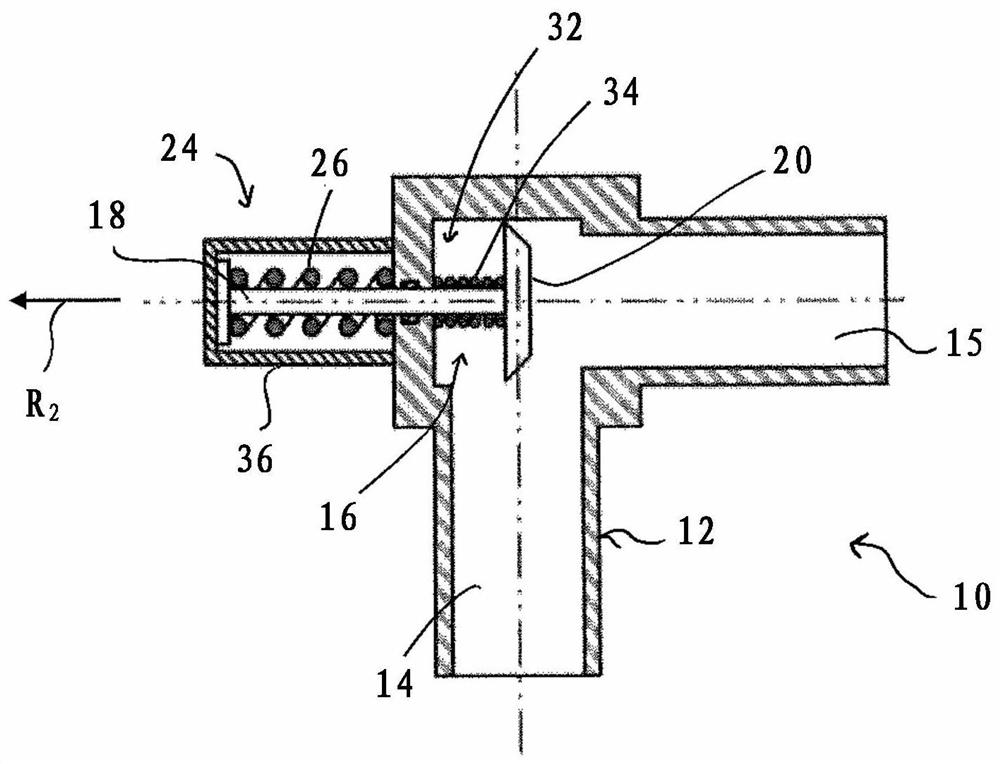
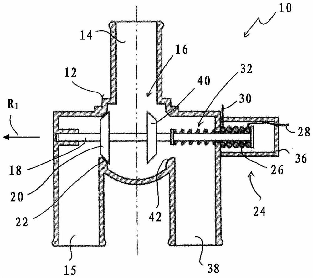
[0027] The valve 10 comprises a valve housing 12 in which two conduit regions 14 , 15 are formed. Arranged in the valve housing 12 is a valve mechanism, generally designated 16 , which has a valve slide 18 extending in the direction of the movement axis A and a conically shaped first valve element 20 in the example shown. Within the meaning of this configuration according to the invention, the valve element 20 , also referred to below only as valve element in connection with this configuration, is the only valve element.

[0028] In the valve housing 12 , a valve seat 22 is assigned to the valve element 20 , eg a correspondingly conical or edge-shaped valve seat 22 . The valve train 16 is po...


PUM


Abstract

The invention relates to a valve, in particular for a heat transfer medium flow circuit in a vehicle, comprising at least one valve element (16) and an actuator arrangement (24) which is associated with the at least one valve element (16) and has at least one shape memory material adjustment element (26, 44).

Description

technical field [0001] The invention relates to a valve which can be used, for example, in a heat transfer medium flow circuit in a vehicle for releasing and interrupting one or more flow paths. Background technique [0002] In vehicles using a heat transfer medium flow circuit for thermal management, the heat transfer medium, usually liquid, is used to dissipate heat from certain system areas, such as the battery, parking heater or heater or the internal combustion engine, and / or to dissipate heat For transmission to other system areas, for example the vehicle interior, electrically actuated solenoid valves are often used in order to release or interrupt the various flow paths, for example in a temperature-dependent manner. Such solenoid valves are relatively heavy and require a relatively large installation space due to the necessity to install the armature / coil subassembly. Contents of the invention [0003] The object of the present invention is to provide a valve whi...

Claims


Application Information

Patent Timeline
IPC IPC(8): F16K1/00F16K1/32F16K11/044F16K31/70
CPCF16K1/00F16K1/32F16K11/044F16K31/002G05D23/27541G05D23/27535F16K31/025F03G7/06F01P2070/02
Inventor M·洪堡H·延森
Owner EBERSPACHER CLIMATE CONTROL SYST GMBH
Why Eureka
Try Eureka