A composite steel box girder for high-speed railway and its construction method
A construction method and technology for high-speed railways, applied in bridge construction, construction, bridges, etc., can solve the problems of increasing hoisting weight, complicated on-site operations, and large width, and achieve the effects of ensuring dynamic stability, facilitating hoisting operations, and increasing frequency.
- Summary
- Abstract
- Description
- Claims
- Application Information
AI Technical Summary
Problems solved by technology
Method used
Image
Examples
Embodiment 1
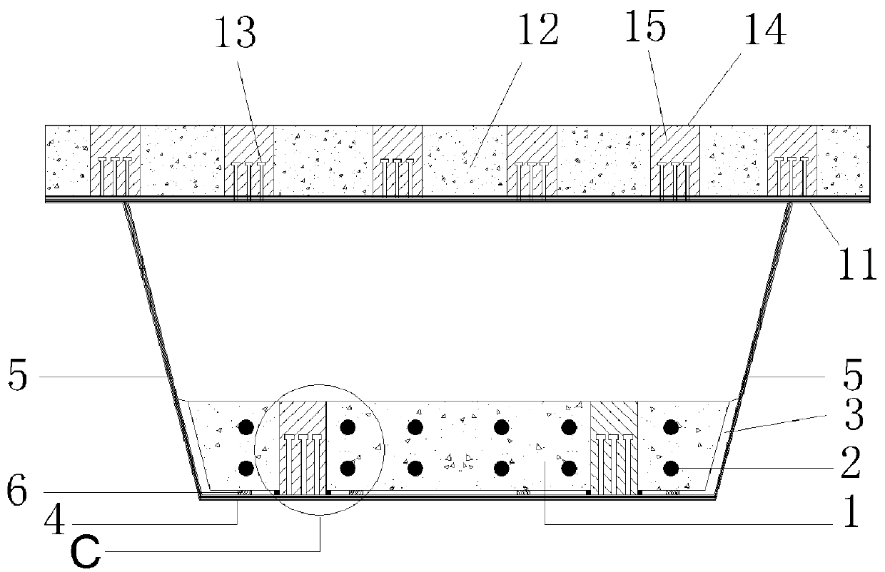
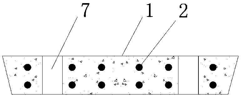
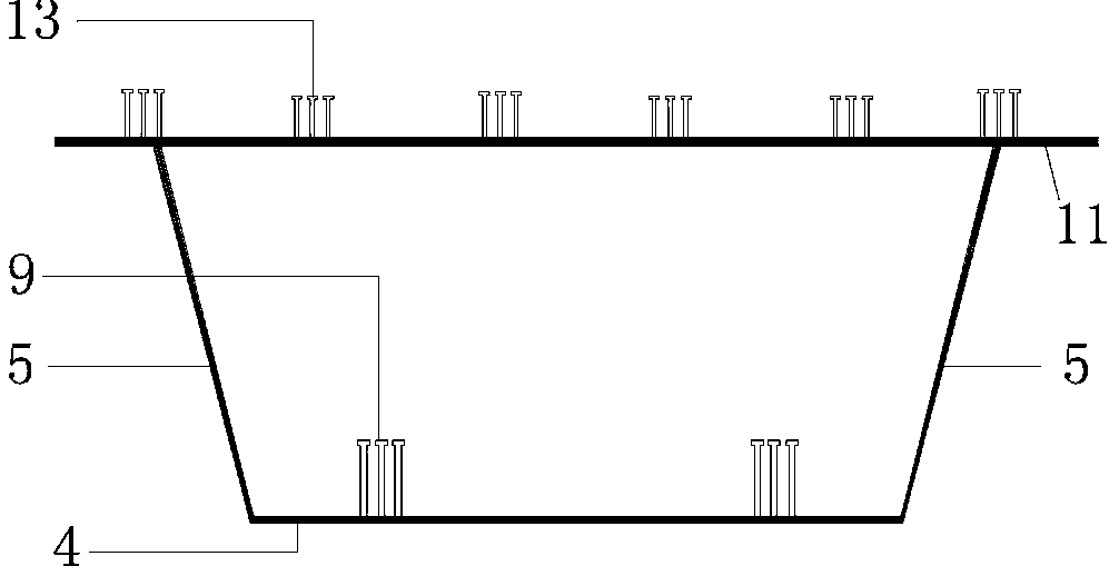
[0038] For the schematic diagram corresponding to this embodiment, see figure 1 , figure 2 , image 3 and Figure 4 . This embodiment is applied to the manufacture and installation of high-speed railway bridges. The steel box in the present invention is composed of a web (5), a steel bottom plate (4) and an upper flange plate (11), and there are upper truss-type diaphragms arranged at a certain distance in the longitudinal direction inside. A prestressed concrete slab (1) is installed inside the steel box, an adhesive layer (3) is arranged between the two, and prestressed tendons (2) are arranged in the prestressed concrete slab (1). A prefabricated concrete roof (12) is connected to the upper flange plate (11), and the two are connected by roof shear nail groups (13) welded on the upper surface of the upper flange plate (11). Correspondingly, a rectangular roof shear groove (14) is reserved on the concrete roof (12), and the roof micro-expansion concrete (15) is poured th...
Embodiment 2
[0046] For the schematic diagram corresponding to this embodiment, see Figure 5 . This embodiment is a modification of Embodiment 1, changing the connection method between the prestressed concrete slab (1) and the steel floor (4). Screw rods (19) are welded on the upper surface of the steel base plate (4), and correspondingly, when the prefabricated prestressed concrete slab (1) is prefabricated, vertical cavities are reserved at corresponding positions thereon. After the prestressed concrete slab (1) is installed, the screw rod (19) is successively installed with a lower backing plate (16), an upper backing plate (17) and a nut (18) from bottom to top. Before the prestressed concrete slab (1) is installed, the lower backing plate (16) is installed earlier, and then the rubber pad is overcoated on the screw rod (19), and falls to the lower backing plate (16) upper surface.
Embodiment 3
[0048] The schematic diagram corresponding to this embodiment is shown in Figure 6 . This embodiment is a modification of the previous embodiment. The concrete roof (12) is constructed by the cast-in-place method. The upper surface of the upper flange plate (11) is welded with shear studs (20). Correspondingly, the step (b) in the construction method is omitted, and the installation of the prefabricated concrete roof (12) in the step (d) is replaced by on-site pouring. This embodiment reduces the workload of prefabrication and installation, but needs to strengthen on-site quality management and correspondingly increases the construction time.
PUM
 Abstract
Description
Claims
Application Information
 - R&D
- Intellectual Property
- Life Sciences
- Materials
- Tech Scout
- Unparalleled Data Quality
- Higher Quality Content
- 60% Fewer Hallucinations
Browse by: Latest US Patents, China's latest patents, Technical Efficacy Thesaurus, Application Domain, Technology Topic, Popular Technical Reports.
© 2025 PatSnap. All rights reserved.Legal|Privacy policy|Modern Slavery Act Transparency Statement|Sitemap|About US| Contact US: help@patsnap.com


