A composite steel box girder and its construction method

A construction method and technology of steel box girder, applied in the field of bridge structure, can solve the problems of increasing hoisting weight, complicated on-site operation, large width, etc., and achieve the effect of ensuring dynamic stability, facilitating hoisting operation, and increasing frequency

Active Publication Date: 2019-11-08
ZHENGZHOU UNIV
View PDF7 Cites 0 Cited by
  • Summary
  • Abstract
  • Description
  • Claims
  • Application Information

AI Technical Summary

Problems solved by technology

Using a steel box as the bottom plate of a steel box girder, pouring concrete or mortar into the interior and then applying prestress is a good method, which can meet engineering applications, but there are still the following disadvantages: most of the prestress is still "consumed" in the On the steel box, and the steel box has strong tensile capacity, this part of the prestress is not needed; the concrete or mortar in the steel box still has problems of shrinkage and creep, and the internal prestress will decrease during use; If the concrete or mortar in the steel box is poured before, the hoisting weight will be increased; if the concrete or mortar in the bottom plate is poured after the steel box is installed in place, and then the prestress is stretched, the construction progress will be affected; because the bottom plate of the steel box is used as a pouring Concrete or mortar formwork determines that its width cannot be large, and a composite beam cannot meet the needs of the entire bridge, and can only be assembled in the form of multiple beams in the horizontal direction, which will complicate the on-site operation and increase the operation time

Method used


Image

  • A composite steel box girder and its construction method
  • A composite steel box girder and its construction method
  • A composite steel box girder and its construction method

Examples


Embodiment 1

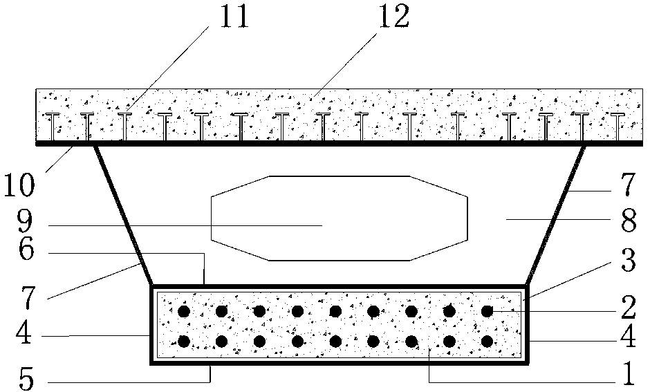
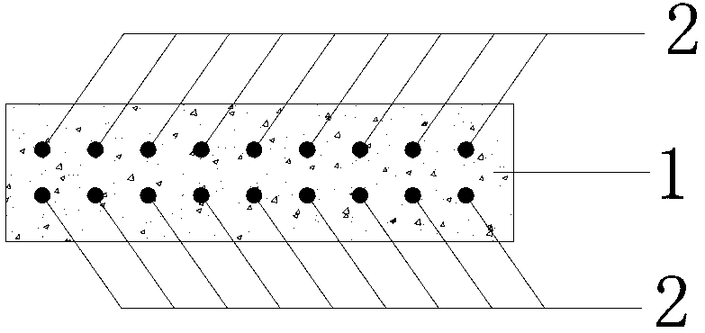
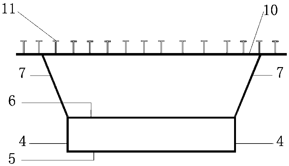
[0036] For the schematic diagram corresponding to this embodiment, see Figure 5. This embodiment is applied to the manufacture and installation of high-speed railway bridges. The steel box in the present invention includes an upper steel box and a lower steel box. The upper steel box is composed of the upper steel box web (7), the two steel box partitions (6) and the upper flange plate (10). There is a manhole (9) in the middle of the steel box transverse partition (8); the lower steel box is composed of the lower steel box web (4), two steel box partitions (6) and the lower steel box bottom plate (5), the lower steel box A prestressed concrete slab (1) is installed inside, a bonding layer (3) is arranged between the two, and prestressed tendons (2) are arranged inside the prestressed concrete slab (1). A prefabricated concrete top plate (12) is connected to the upper flange plate (10), and the two are connected through cluster shear studs (14) welded on the upper surface ...

Embodiment 2

[0045] For the schematic diagram corresponding to this embodiment, see Figure 4 , applied to urban bridges, the number of bridge spans in the corresponding project is relatively small. This embodiment is a modification of Embodiment 1. The concrete roof (12) is constructed by the cast-in-place method, and the upper surface of the upper flange (10) is welded with stud connectors (11). Correspondingly, the step (b) in the construction method is omitted, and the installation of the prefabricated concrete roof (12) in the step (d) is replaced by on-site pouring. After pouring, it should be maintained for 7 days according to the construction requirements before the next step of construction can be carried out. The manufacture of the upper steel box is the same as the conventional steel box girder, and U-shaped channel steel members are welded under the bottom plate to form the lower steel box. This embodiment reduces the workload of prefabrication and installation, but needs to ...

Embodiment 3

[0047] The schematic diagram corresponding to this embodiment is shown in figure 1 , figure 2 and image 3 . This embodiment is a modification of Embodiment 2. Mainly because the bottom of the fastening bolt (13) is outside the lower surface of the lower steel box floor (5), that is, the outer side of the steel box, which affects the appearance, it is canceled, thereby simplifying prefabrication and on-site construction.


PUM


Abstract

The invention discloses a combined steel box girder and a construction method thereof, belonging to the field of high-speed railway bridges. A steel box of the combined steel box girder comprises adjacent upper steel box and a lower steel box sharing one horizontal separating plate; a prefabricated prestressed concrete plate is glued to the inner of the lower steel box with structural glue. The prestressed concrete plate passes through the lower steel box and the peripheral gap is filled with structural glue. Since the girder is made of the steel box, a concrete top board and the prestressed concrete plate inside the lower steel box, the girder can be assembled on site, which is convenient for transportation and hoisting for construction and it is possible to build simply supported beams with larger span. Compared with present whole simple girders of the same span, the provided combined steel box girder has increased cross section rigidity of the steel box girder, the weight of girders is reduced and the span of girders is increased. The combined steel box girder of the invention has reasonable construction stress and is convenient to construct; the method is applied for building high speed railway beam bridges with larger span.

Description

technical field [0001] The invention relates to a composite steel box girder and a construction method thereof, which belong to the technical field of bridge structures and are mainly applied to high-speed railway bridges. Background technique [0002] At present, in the field of high-speed railways, simply supported beam bridges mostly use T-shaped section beams or box-shaped section beams. The former is referred to as T-beam and the latter is referred to as box girder. Because the T-beam bridge composed of T-beams has small lateral stiffness, poor torsion resistance, and poor stability during installation, the on-site operation time is long, so it is not suitable for use with large spans. Simply supported girder bridges with longer spans generally use box girders. [0003] Box girders include concrete box girders, steel box girders and composite steel box girders. When the span is large, the weight of the concrete box girder is very heavy, which brings difficulty to pour...

Claims


Application Information

Patent Timeline
Patent Type & Authority Patents(China)
IPC IPC(8): E01D2/04E01D21/00E01D101/28
CPCE01D2/04E01D21/00E01D2101/285
Inventor 魏建东
Owner ZHENGZHOU UNIV
Why Eureka
Try Eureka