Injection mould

An injection mold and movable mold technology, applied in the field of injection molds, can solve the problems of low product yield and reduced production efficiency.

Inactive Publication Date: 2017-09-01
HUANGSHI HONGXING PLASTIC MOLD
View PDF0 Cites 5 Cited by
  • Summary
  • Abstract
  • Description
  • Claims
  • Application Information

AI Technical Summary

Problems solved by technology

[0002] At present, the injection molds used to produce grille products such as automobile grilles generally set the gate on the outer surface of the product, so that there will be injection points on the outer surface of the product, and then image the appearance of the product; if the gate is set on the side of the product If the side-feeding method is adopted, the injection-molded product needs to be trimmed manually, and the material handle is cut off from the product, which greatly reduces the production efficiency, and the product yield is not high.

Method used


Image

  • Injection mould
  • Injection mould
  • Injection mould

Examples


Embodiment Construction

[0014] The present invention will be further described below in conjunction with accompanying drawing.

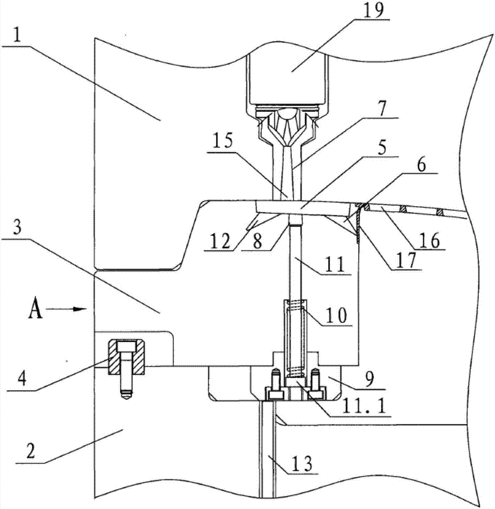
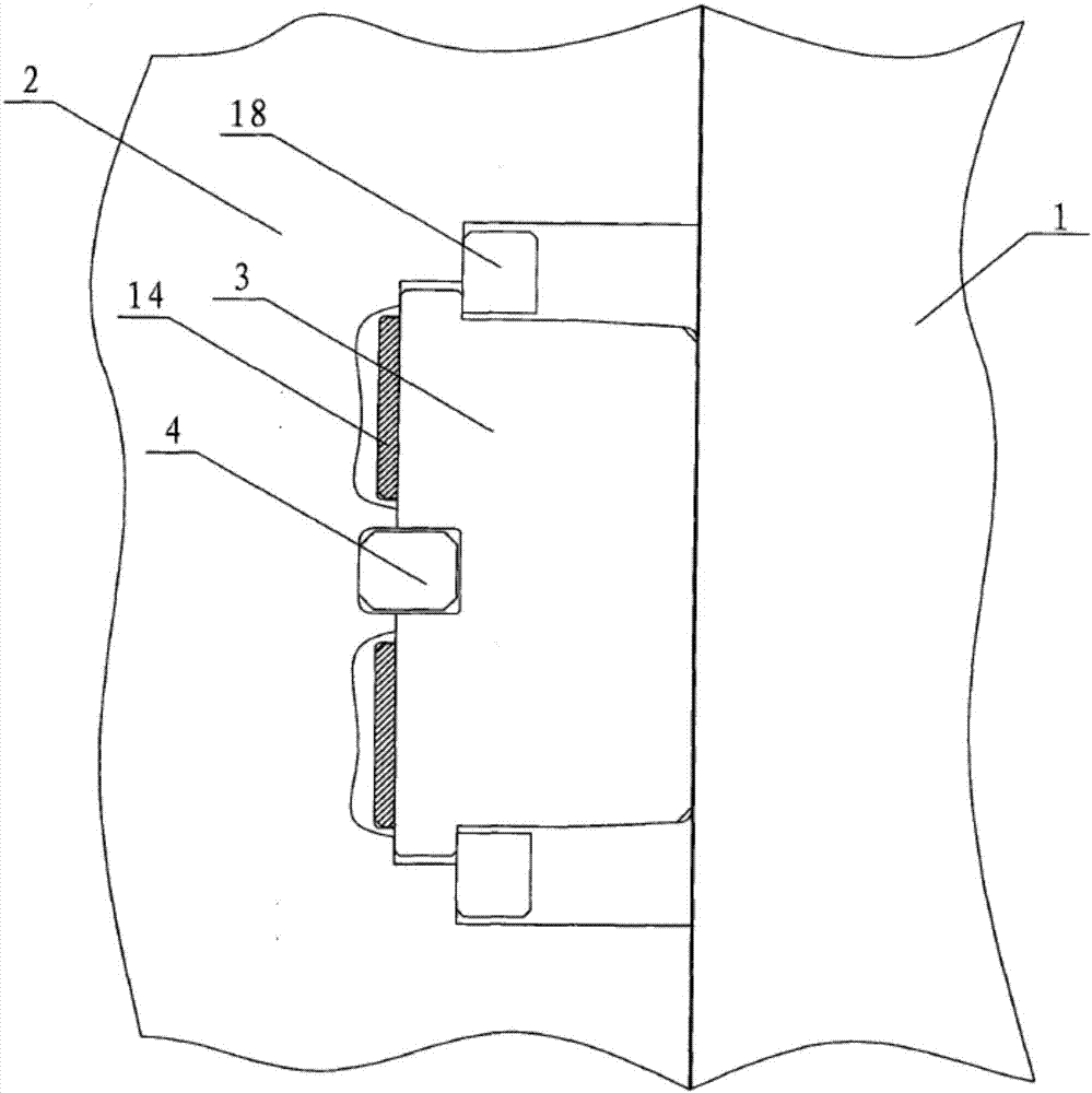
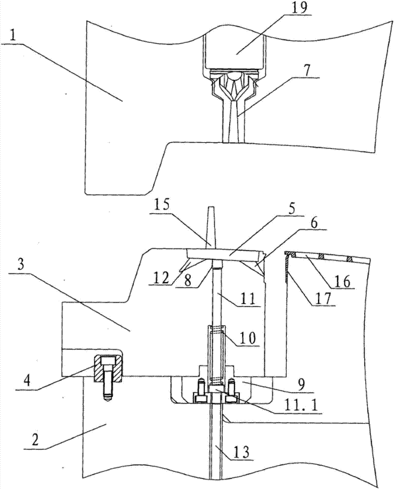
[0015] The injection mold of the present invention comprises a static mold 1 and a power mold 2, the movable mold 2 is provided with a slider 3 and a limit block 4 for limiting the sliding distance of the slider 3, and the slider 3 is provided with a flow channel 5. Gate I6, the ejector device for item discharge handle 15: the slider 3 is slidably connected with the movable mold 2, the limit block 4 is fixedly connected with the movable mold 2 by bolts; the runner 5 It communicates with the gate I6, and the runner 5 also communicates with the main channel 7 of the static mold 1; the gate I6 communicates with the core wall 17, that is to say, the gate I6 is located at the inner wall of the product; the gate I6 communicates with the inner wall of the product; The ejector device is installed in the slide block 3 , and the item outlet 8 of the ejector device communicates with t...


PUM


Abstract

The invention discloses an injection mold which has no injection point on the outer surface of the product and does not need to manually trim the product. It includes a static mold and a moving mold, and the moving mold is provided with a slider and a limit block for limiting the sliding distance of the slider. , the slider is provided with runners, gate 1, and an ejector for ejecting the material handle; the slider is slidably connected with the movable mold, and the limiting block is fixedly connected with the movable mold; the runner It communicates with the gate I, and the runner also communicates with the main channel of the static mold; the gate I communicates with the core wall; the ejector device is installed in the slider, and the ejector port of the ejector device is connected to the The runners are connected.

Description

technical field [0001] The present invention relates to an injection mold for producing grille products such as automobile grilles. Background technique [0002] At present, the injection molds used to produce grille products such as automobile grilles generally set the gate on the outer surface of the product, so that there will be injection points on the outer surface of the product, and then image the appearance of the product; if the gate is set on the side of the product If the side-feeding method is adopted, the injection-molded product needs to be trimmed manually, and the material handle is cut off from the product, which greatly reduces the production efficiency, and the product yield is not high. Contents of the invention [0003] The technical problem to be solved by the present invention is to provide an injection mold with no injection point on the outer surface of the product and no manual trimming of the product. [0004] The technical solution of the prese...

Claims


Application Information

Patent Timeline
IPC IPC(8): B29C45/27B29C45/33B29C45/38B29C45/40
CPCB29C45/2708B29C45/332B29C45/38B29C45/401B29C2045/0027B29C2045/2709
Inventor 张红平刘守华邹昌明邓坤东程晓华
Owner HUANGSHI HONGXING PLASTIC MOLD
Why Eureka
Try Eureka