Image-based Head Rotation Strabismus Measurement System

A measurement system and imaging technology, applied in the field of medical devices, can solve the problems of comparison of eye recovery conditions, unfavorable for patients, and patients' inability to intuitively understand the state of the disease, etc., to achieve the effect of accurate strabismus

Active Publication Date: 2019-04-02
张聪
View PDF7 Cites 0 Cited by
  • Summary
  • Abstract
  • Description
  • Claims
  • Application Information

AI Technical Summary

Problems solved by technology

If you have binocular vision, you can combine the images from both eyes into one and feel it as one object. If you don’t have binocular vision, you can use the scale on the synoptic machine panel to understand the patient’s strabismus and analyze other data. ; The procedure for measuring strabismus with the synoptic machine is complicated, and the image data cannot be retained, and the disease can only be recorded as data, so the patient cannot intuitively understand the state of the disease; it is also not conducive to the patient's eye recovery before and after surgery. Compared

Method used


Image

  • Image-based Head Rotation Strabismus Measurement System
  • Image-based Head Rotation Strabismus Measurement System
  • Image-based Head Rotation Strabismus Measurement System

Examples


Embodiment 1

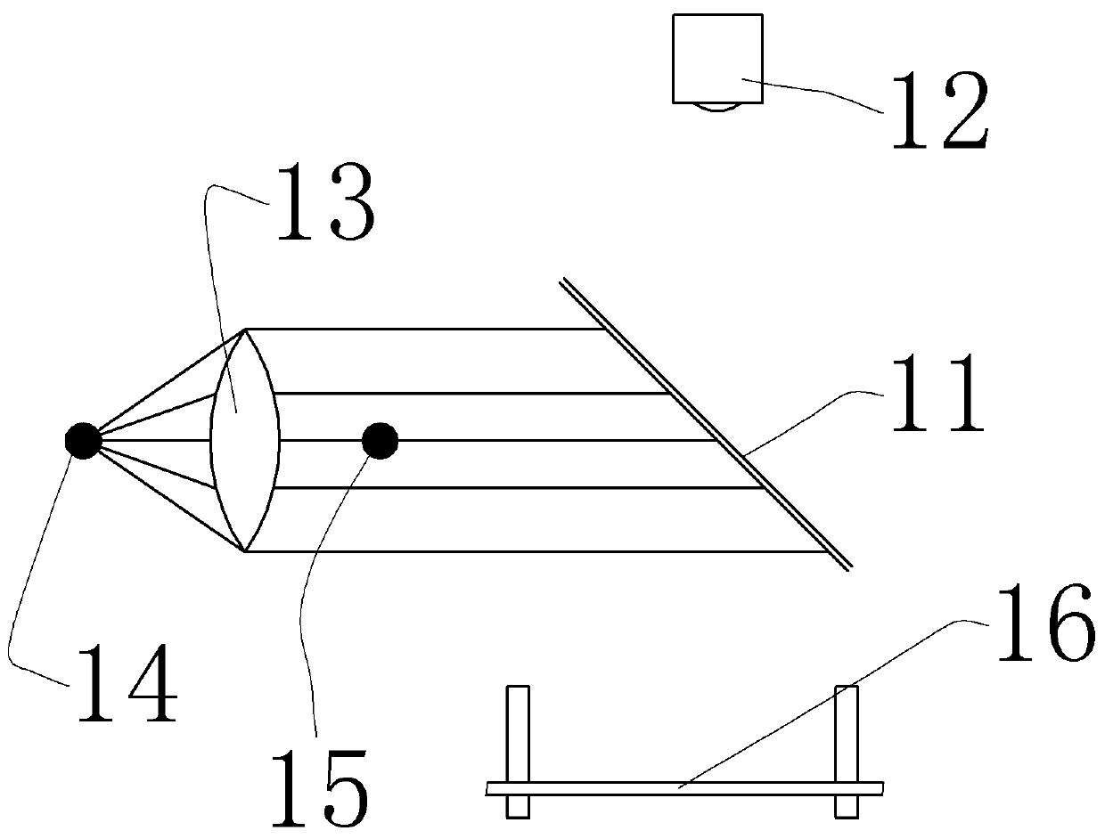
[0025] Such as figure 1 As shown, the image-based head rotation squint measurement system includes a high-definition camera 12 for photographing the position of the pupil of the eye and the reflective point on the cornea; a surface light source that emits white light for illuminating the eye and is arranged in front of the high-definition camera 12, The center of the surface light source is provided with a gazing light source that emits red light for the subject to stare at, and in this embodiment, the luminance of the gazing light source is lower than that of the surface light source. A supporting device for supporting the subject's head. The supporting device includes a fixed bracket relative to the gazing light source and a bracket 16 slidably connected to the bracket. The bracket is provided with a sliding surface that can be parallel to the coronal plane of the subject, and the bracket 16 can move circularly around the center line perpendicular to the sliding surface by s...

Embodiment 2

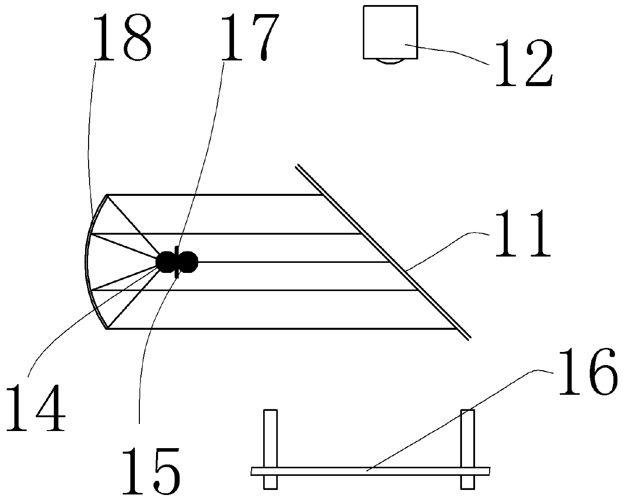
[0030] Such as figure 2 , the difference between the second embodiment and the first embodiment is that the convex lens 13 is replaced by a concave mirror 18 in the second embodiment, and the second point light source 14 faces the concave mirror 18. Likewise, the second point light source 14 passes through the concave mirror 18 The formed parallel light is irradiated on the one-way mirror 11 . The place ahead of the concave mirror 18 is provided with a shading plate 17, the second point light source 14 is located between the shading plate 17 and the concave mirror 18, the second point light source 14 is fixed on one side of the shading plate 17, and the other side of the shading plate 17 is fixed with The first point light source 15 and the staring light source are the imaging of the first point light source 15 on the one-way perspective mirror 11 . A shadow can be formed in the center of the surface light source by setting the shading plate 17, thereby setting the first poi...


PUM


Abstract

The invention discloses a head position turning strabismus measurement system based on images and relates to a medical instrument. The head position turning strabismus measurement system comprises a high-definition camera for shooting eye pupil positions and reflective spots on the corneas, a face light source for irradiating the eyes and arranged in front of the high-definition camera, a supporting device for supporting the head of a subject, and a camera supporting frame supporting the high-definition camera, wherein the center of the face light source is provided with a bright-colored staring light source for a subject to stare, the supporting device comprises a support fixed with respect to the staring light source and a bracket connected to the bracket in a sliding mode, a sliding face parallel to the coronal plane of the subject is arranged on the support, the bracket can slide on the sliding face of the support, and the high-definition camera is connected to the camera supporting frame in a sliding mode and is fixed with respect to the bracket. By adopting the device, images of the eyes of a strabismus patient can be retained, and accordingly pre-operative and postoperative comparison is promoted. In addition, data of a strabismus state of responding eyes in more directions can be also obtained.

Description

technical field [0001] The invention relates to a medical device, in particular to an image-based head rotation strabismus measurement system. Background technique [0002] The current measurement methods for strabismus mainly include 33cm corneal light reflection method and synoptic machine measurement method; the 33cm corneal light reflection method is to place the light 33cm in front of the patient and observe the light reflection point on the patient's cornea. The corneal light reflection point of the non-fixating eye is located at the pupillary edge, which is equivalent to a 15° deviation of the eye position; the corneal light reflection point is located between the pupil limbus and the corneal limbus, which is equivalent to a 30° deviation; the light reflection point is located at the corneal limbus, which is equivalent to a deviation 45°. Corneal photometry is a rough method for checking dominant corotating strabismus, which is more suitable for young children and pa...

Claims


Application Information

Patent Timeline
Patent Type & Authority Patents(China)
IPC IPC(8): A61B3/08
CPCA61B3/0008A61B3/085
Inventor 张聪
Owner 张聪
Why Eureka
Try Eureka