
Method and system for displaying speed limit information

A technology of prompting information and subsystems, applied to the arrangement of variable traffic instructions, measuring devices, instruments, etc., can solve problems such as untimely adjustment of speed limit values, low compliance rate of speed limit values, unreasonable and other problems, and achieve the goal of solving the limit The effect of unreasonable speed value

Inactive Publication Date: 2017-09-08
北京中交华安科技有限公司 +1
View PDF26 Cites 11 Cited by
  • Summary
  • Abstract
  • Description
  • Claims
  • Application Information

AI Technical Summary

Problems solved by technology

However, if there is no continuous power supply cable near the traffic road (for example, some expressways), technicians need to pull the cable to the variable speed limit signboard from a distance, so as to realize the supply of electricity to the variable speed limit signboard in the form of mains power supply. Variable speed limit signboard power supply, which increases the economic cost of building the variable speed limit signboard
[0004] Considering the high economic cost of building variable speed limit signs on such traffic roads, variable speed limit signs are usually not built on such traffic routes at present, which leads to the practical application range of variable speed limit signs Small
In addition, the speed limit value in the variable speed limit sign is usually manually adjusted by the staff of the traffic command center based on experience, which is prone to the problem of untimely and unreasonable adjustment of the speed limit value
Moreover, the variable speed limit sign only includes the speed limit value, and does not prompt or not prompt the driver to adopt the current speed limit value at the same time, which will easily lead to a low rate of compliance with the speed limit value

Method used


Image

  • Method and system for displaying speed limit information
  • Method and system for displaying speed limit information
  • Method and system for displaying speed limit information

Examples


Embodiment Construction

[0050] Reference will now be made in detail to the exemplary embodiments, examples of which are illustrated in the accompanying drawings. When the following description refers to the accompanying drawings, the same numerals in different drawings refer to the same or similar elements unless otherwise indicated. The implementations described in the following exemplary examples do not represent all implementations consistent with the present disclosure. Rather, they are merely examples of apparatuses and methods consistent with aspects of the present disclosure as recited in the appended claims.

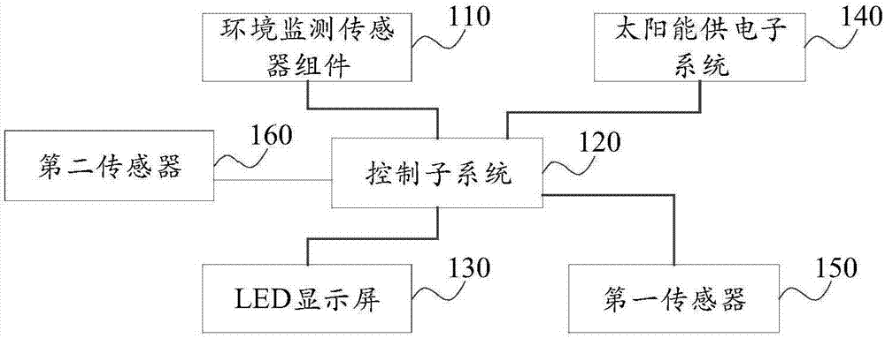
[0051] figure 1 It is a structural schematic diagram of a system for displaying speed limit information according to an exemplary embodiment, the system includes an environment monitoring sensor assembly 110, a control subsystem 120, an LED display 130, a solar power supply subsystem 140 and a first sensor 150 ,in:

[0052] The environmental monitoring sensor assembly 110 is used to ...


PUM


Abstract

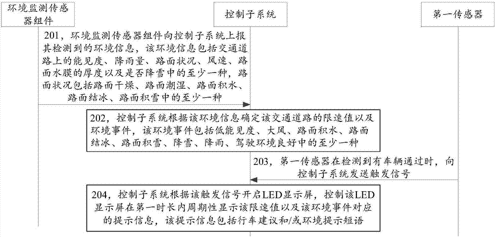
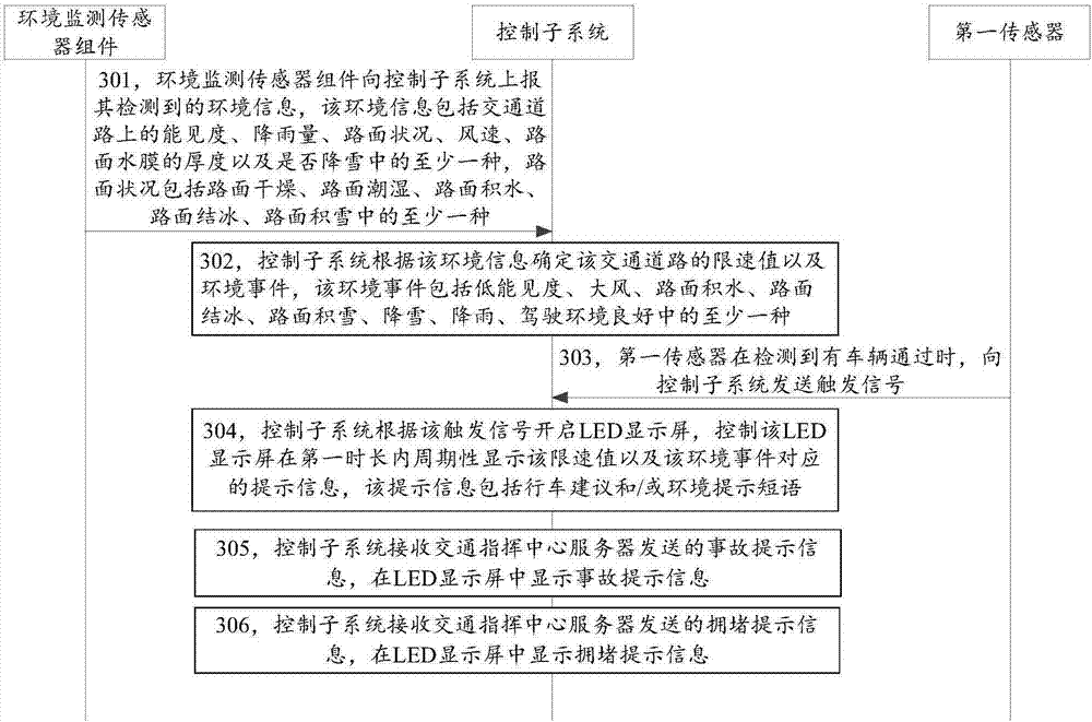
The invention discloses a method and system for displaying speed limit information and belongs to a field of road traffic. The method is applied to the system including an environment monitoring sensor assembly, a control sub system, an LED display screen, a solar power supply sub system and a first sensor. The solar power supply sub system supplies power to other parts in the system. The method includes that the environment monitoring sensor assembly reports monitored environment information to the control sub system; the control sub system determines a speed limit value and an environment event of a traffic road according to the environment information; the first sensor sends a triggering signal to the control sub system when detecting a vehicle passing by; the control sub system switches on the LED display screen according to the triggering signal and controls the LED display screen to display the speed limit value and prompt information corresponding to the environment event periodically in a first time length. According to the invention, effects of reducing power consumption of the LED display screen, determining the speed limit value reasonably, regulating the speed limit value timely and enlarging the application range of the LED display screen are achieved.

Description

technical field [0001] The present disclosure relates to the field of highway traffic, in particular to a method and system for displaying speed limit information. Background technique [0002] Speed ​​limit is an important technical means in road traffic management. At present, variable speed limit signs (variable speed limit sign, VSLS) can be set up beside traffic roads, such as light-emitting diode (Light Emitting Diode, LED) variable speed limit signs, which can display the traffic The speed limit value of the road at this time. [0003] At present, when a variable speed limit signboard is built beside a traffic road, the variable speed limit signboard is powered by the mains power supply to ensure the normal operation of the variable speed limit signboard and the constant speed limit value. show. However, if there is no continuous power supply cable near the traffic road (for example, some expressways), technicians need to pull the cable to the variable speed limit ...

Claims


Application Information

Patent Timeline
IPC IPC(8): G08G1/09G09F9/33G01D21/02
CPCG01D21/02G08G1/09G09F9/33
Inventor 李长城辛欣文涛韩晖廖文洲汤筠筠谭一鸣仝龙飞
Owner 北京中交华安科技有限公司
Learn More