Cable marking machine

A marking machine and cable technology, applied in printing machines, printing devices, rotary printing machines, etc., can solve the problems of high use and maintenance costs, inability to be widely used, and occupy a large area, and achieve low input cost, easy replacement, Good sealing effect

Inactive Publication Date: 2017-09-12
天津市电缆总厂第一分厂
View PDF9 Cites 2 Cited by
  • Summary
  • Abstract
  • Description
  • Claims
  • Application Information

AI Technical Summary

Problems solved by technology

[0002] Cables are widely used in the electric power industry. They are mainly used for power transmission. During the production process of cables, the surface of the cables needs to be marked. Marking once at a certain distance, the existing cable marking is mainly divided into automatic marking and manual marking, manual marking is gradually being eliminated due to low efficiency, low precision and time-consuming and laborious, while automatic marking devices are due to high marking accuracy, The production efficiency is high and manual marking is gradually replaced, but the existing automatic marking device cannot be widely used due to the high cost of use and maintenance, complicated operation, and relatively large occupied area.

Method used


Image

  • Cable marking machine
  • Cable marking machine
  • Cable marking machine

Examples


Embodiment Construction

[0020] The preferred embodiments of the present invention will be described in detail below in conjunction with the accompanying drawings, so that the advantages and features of the present invention can be more easily understood by those skilled in the art, so as to define the protection scope of the present invention more clearly.

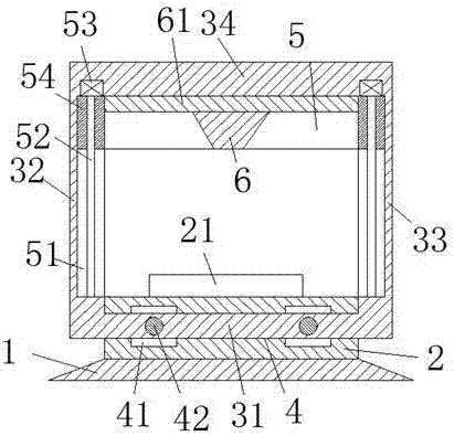
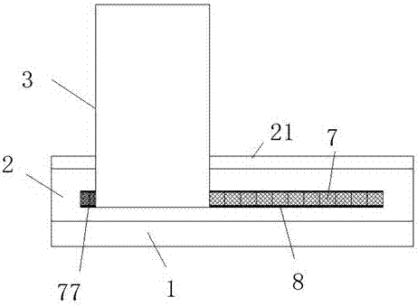
[0021] refer to Figure 1-6 A cable marking machine shown includes a carrier plate 2 and a moving carriage 3 that is slidingly fitted and connected with the carrier plate 2. A platform 1 is provided at the bottom of the carrier plate 2. There is a sliding groove 4 communicating with the left and right. The sliding frame 3 includes a bottom straight wall 31 that is slidingly fitted with the sliding groove 4, and is arranged on the left end of the bottom straight wall 31 and is connected to the bearing plate 2. The left straight wall 32 connected with the sliding fit of the left end face, and the right straight wall 33 arranged at the right end of ...


PUM


Abstract

The invention discloses a cable marking machine. The cable marking machine comprises a bearing plate and a sliding frame connected with the bearing plate in a sliding matched manner. A bearing platform is arranged on the bottom of the bearing plate. A left-right through sliding groove is formed in the bearing plate. The sliding frame comprises a bottom straight wall connected with the sliding groove in a sliding matched manner, a left straight wall which is arranged at the left end of the bottom straight wall and connected with the left end face of the bearing plate in a sliding matched manner and a right straight wall which is arranged at the right end of the bottom straight wall and connected with the right end face of the bearing plate in a sliding matched manner. The cable marking machine is simple in overall structure, low in invested cost and easy and convenient to operate; and a first motor works to provide power drive for a marking gun at the front and rear positions, a second motor works to provide power drive for the marking gun at the upper and lower positions, and therefore the accuracy of cable marking and uniformity of marks after a cable is marked are guaranteed, the marking efficiency is high, the production efficiency is greatly improved, and the cable marking machine is suitable for being used and popularized.

Description

technical field [0001] The invention relates to the technical field of cables, in particular to a cable marking machine. Background technique [0002] Cables are widely used in the electric power industry. They are mainly used for power transmission. During the production process of cables, the surface of the cables needs to be marked. Marking once at a certain distance, the existing cable marking is mainly divided into automatic marking and manual marking, manual marking is gradually being eliminated due to low efficiency, low precision and time-consuming and laborious, while automatic marking devices are due to high marking accuracy, The production efficiency is high and manual marking is gradually replaced. However, the existing automatic marking device cannot be widely used due to the high cost of use and maintenance, complicated operation, and relatively large occupied area. Contents of the invention [0003] The technical problem to be solved by the present inventio...

Claims


Application Information

Patent Timeline
Patent Type & Authority Applications(China)
IPC IPC(8): B41F17/12
CPCB41F17/12B41P2217/50
Inventor 斯幼云
Owner 天津市电缆总厂第一分厂
Why Eureka
Try Eureka