
Refrigerant cooling main control board condensation preventing device and method and air conditioner unit

A refrigerant heat dissipation and main control board technology, applied in the field of air conditioners, can solve the problems of insignificant anti-condensation effect and slow temperature change process, and achieve the effect of remarkable anti-condensation effect, less refrigerant volume, and quick adjustment.

Inactive Publication Date: 2017-09-12
GREE ELECTRIC APPLIANCES INC
View PDF6 Cites 8 Cited by
  • Summary
  • Abstract
  • Description
  • Claims
  • Application Information

AI Technical Summary

Problems solved by technology

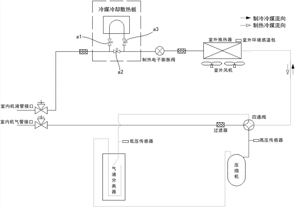
However, this method of controlling the amount of refrigerant flowing through the refrigerant cooling heat sink in the heating mode is to adjust the amount of refrigerant at the refrigerant outflow end of the refrigerant cooling heat sink, and the process of controlling the temperature change is relatively slow. When exposed, even if the control valve a3 is completely closed, the control valve a1 is still fully open, the amount of refrigerant in the refrigerant cooling plate has not decreased, but the flow has changed, and the refrigerant will continue to cool for a period of time The cooling plate will continue to generate condensation, and the anti-condensation effect is not significant

Method used


Image

  • Refrigerant cooling main control board condensation preventing device and method and air conditioner unit
  • Refrigerant cooling main control board condensation preventing device and method and air conditioner unit
  • Refrigerant cooling main control board condensation preventing device and method and air conditioner unit

Examples


Embodiment approach

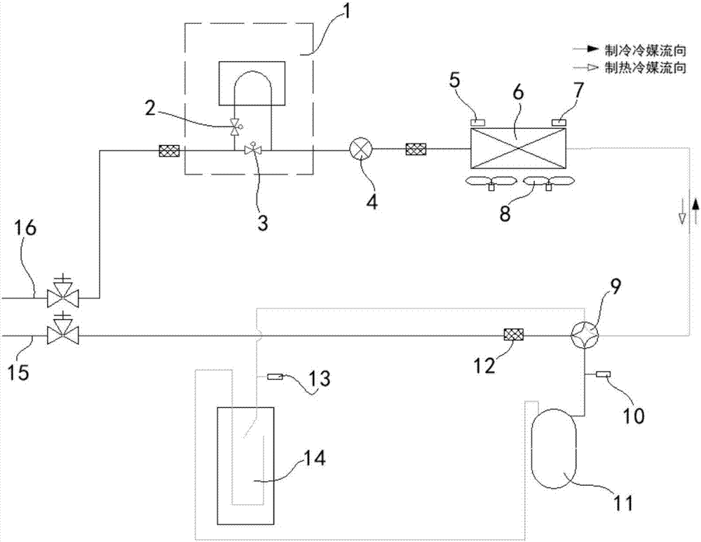
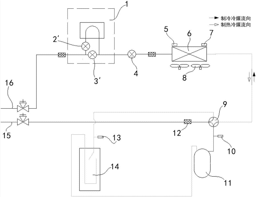
[0044] In the following, the first and second preferred embodiments of the anti-condensation device for the main control board of refrigerant heat dissipation are taken as examples to illustrate the first and second preferred implementation modes of the anti-condensation method for the main control board of refrigerant heat dissipation of the present invention as follows:

[0045] 1. The first preferred embodiment (such as Figure 4 shown, corresponding to figure 2 Shown embodiment) as shown in table 1:

[0046] Table 1

[0047]

[0048]

[0049] 2. The second preferred embodiment (such as Figure 5 shown, corresponding to image 3 Shown embodiment) as shown in table 2:

[0050] Table 2

[0051]

[0052] Among them, pls represents the measurement unit of the number of opening steps, T 1 Main control board temperature, T 0 For the corrected temperature value, T 2 is the dew point temperature; the corrected temperature value T0 is a configurable parameter, whic...


PUM


Abstract

The invention relates to an anti-condensation device and method for a refrigerant heat dissipation main control board and an air conditioner unit, wherein the anti-condensation device for a refrigerant heat dissipation main control board includes: a detection mechanism and a control mechanism, and the detection mechanism is used to detect whether the refrigerant heat dissipation main control When condensation occurs, the regulating mechanism is used to reduce the amount of refrigerant flowing into the refrigerant heat dissipation main control board from the refrigerant inflow end of the refrigerant heat dissipation main control board when the detection mechanism detects condensation on the refrigerant heat dissipation main control board in the heating mode, to eliminate condensation. By reducing the amount of refrigerant flowing into the refrigerant heat dissipation main control board at the refrigerant inflow end from the refrigerant heat dissipation main control board, the present invention is compared with the existing adjustment method of controlling the amount of refrigerant flowing through the refrigerant cooling heat dissipation plate from the outflow end. On the end, the amount of refrigerant flowing into the refrigerant cooling plate is reduced, and the amount of refrigerant per unit capacity in the refrigerant cooling plate is reduced, which avoids the retention of refrigerant in the refrigerant cooling plate, makes the adjustment faster, and has a significant anti-condensation effect.

Description

technical field [0001] The invention relates to the technical field of air conditioners, in particular to an anti-condensation device and method for power components of an air conditioner unit and an air conditioner unit. Background technique [0002] At present, most indoor multi-connected air-conditioning units adopt refrigerant cooling technology. The temperature module of the main control board of the cooling unit improves the reliability of the related main control equipment during the operation of the unit. When the cooling temperature is lower than the air dew point temperature, condensation water is likely to form around the heat sink, which will affect the heat dissipation of the main control board and cause the risk of damage or even burning of the main control board. [0003] In order to prevent the generation of condensation water, such as figure 1 As shown, in the heating operation process of the refrigerant cooling flow path unit adopted by the existing multi-...

Claims


Application Information

Patent Timeline
Patent Type & Authority Applications(China)
IPC IPC(8): F25B49/02
CPCF25B49/02F25B2600/2515F25B2600/2519F25B2700/02F25B2700/2103F25B2700/2106
Inventor 黄志光周冰焦华超
Owner GREE ELECTRIC APPLIANCES INC
Learn More