Zipper head and zipper

A zipper head, zipper technology, applied in the direction of sliding fastener elements, applications, fasteners, etc., to reduce unusable and improve service life

Pending Publication Date: 2017-09-15
唐昭斌
View PDF9 Cites 1 Cited by
  • Summary
  • Abstract
  • Description
  • Claims
  • Application Information

AI Technical Summary

Problems solved by technology

[0003] The invention provides a zipper puller and a zipper, aiming to solve the above-mentioned problems existing in the zipper puller and the zipper in the prior art

Method used


Image

  • Zipper head and zipper
  • Zipper head and zipper
  • Zipper head and zipper

Examples


Embodiment 1

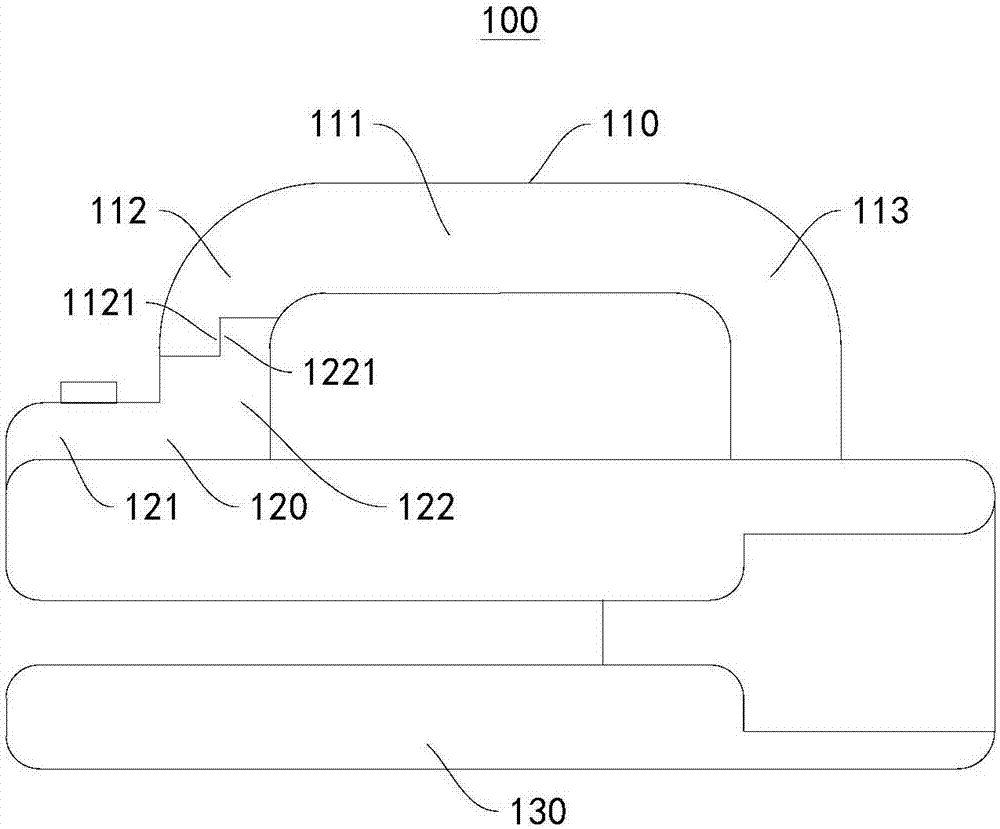
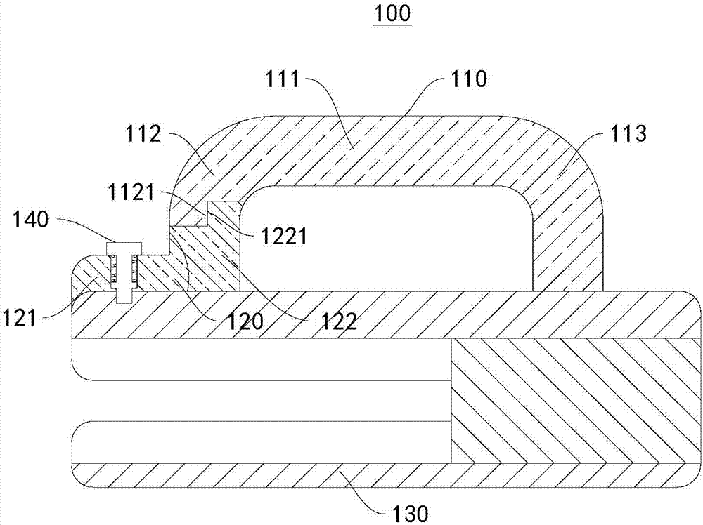
[0040] This embodiment provides a zipper slider 100, please refer to figure 1 , figure 2 , image 3 and Image 6 , the zipper puller 100 includes a zipper body 130 , a cap 110 and a stopper 120 , the zipper body 130 is connected to the cap 110 , and the zipper body 130 is connected to the stopper 120 .

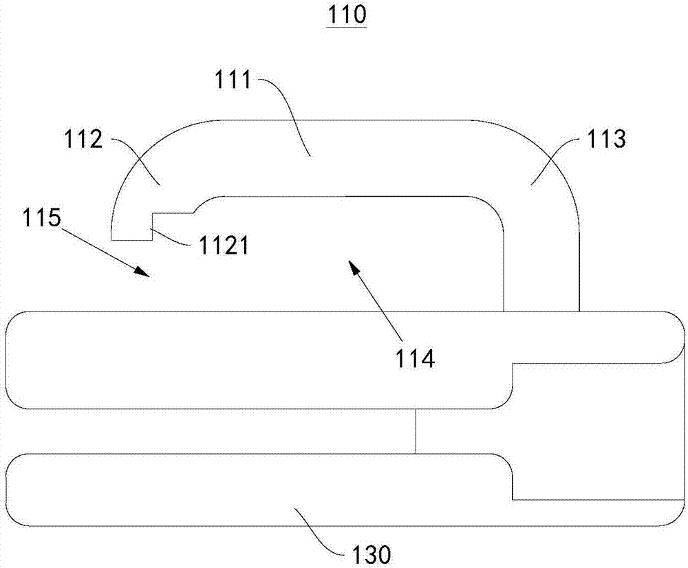
[0041]The cap 110 comprises a cap body 111, a first end 113 and a second end 112, the first end 113 is connected to the zipper body 130, a channel space 115 is formed between the second end 112 and the zipper body 130, the cap body 111 and the zipper An accommodation space 114 is formed between the bodies 130 .

[0042] The stopper 120 has a connection part 121 and a stopper part 122 , the connection part 121 is connected to the stopper part 122 , the connection part 121 is used to connect with the zipper body 130 , and the stopper part 122 is used to block the channel space 115 .

[0043] The connecting portion 121 is detachably connected to the zipper body 130 .

[004...

Embodiment 2

[0061] This embodiment provides a zipper slider 100, please refer to Figure 8 , Figure 9 , Figure 10 and Figure 11 , the zipper puller 100 provided in this embodiment is substantially the same as the zipper puller 100 provided in Embodiment 1, the difference is that the connecting device 140 on the zipper puller 100 provided in this embodiment adopts another form, specifically:

[0062] The connecting device 140 includes a slider 160, the slider 160 is connected to the connecting portion 121, the zipper body 130 has a guide groove 150, the guide groove 150 and the cap 110 are oppositely arranged, the slider 160 and the guide groove 150 are slidably connected, and the guide groove 150 is close to One side of the cap 110 has a first opening 151, and the other side of the guide groove 150 has a second opening 153. There is a connecting channel 152 between the first opening 151 and the second opening 153, and the slider 160 can pass through the connecting channel through the...

Embodiment 3

[0069] This embodiment provides a zipper 200, please refer to Figure 12 , including a zipper strip 200 and the zipper puller 100 provided in the above-mentioned embodiment, the zipper strip 200 and the zipper puller 100 are detachably connected.

[0070] The working principle of the zipper 200 provided in this embodiment is that, when working, due to the detachable connection between the stopper 120 on the zipper puller 100 and the zipper body 130, the pull ring can be replaced, thereby improving the zipper pull. The service life of the zipper 100 can be reduced, thereby reducing the situation that the zipper 200 cannot be used due to the damage of the zipper slider 100.


PUM


Abstract

The invention provides a zipper head and a zipper, and belongs to the field of bag and clothing appliances. The zipper head comprises a zipper body, a cap and a stopper, and the zipper body is connected with the cap and the stopper; the cap comprises a cap body, a first end and second end, the first end is connected with the zipper body, a channel space is formed between the second end and the zipper body, and a containing space is formed between the cap body and the zipper body; the stopper is provided with a connecting part and a stopping part which are connected with each other, the connecting part is used for being connected with the zipper body, and the stopping part is used for blocking the channel space; the connecting part is detachably connected with the zipper body. The zipper comprises a zipper tape and the zipper head, and the zipper tape is detachably connected with the zipper head. According to the zipper head and the zipper, a pull ring is convenient to disassemble, and the service life is longer.

Description

technical field [0001] The invention relates to the field of bags and clothing appliances, in particular to a zipper slider and a zipper. Background technique [0002] At present, the use of zippers in people's daily life is very common, but when the zipper is in use, due to the need to frequently pull the zipper head through the pull ring, the chain teeth on the zipper are approached or far away from each other, and the chain teeth are frequently pulled During the process, the pull ring will be damaged. The pull ring in the prior art is usually set in a non-detachable form. When the pull ring is damaged, it is inconvenient to replace. Contents of the invention [0003] The present invention provides a zipper puller and a zipper, aiming at solving the above-mentioned problems existing in the zipper puller and the zipper in the prior art. [0004] The present invention is achieved like this: [0005] A zipper puller, comprising a zipper body, a cap and a stopper, the zipp...

Claims


Application Information

Patent Timeline
Patent Type & Authority Applications(China)
IPC IPC(8): A44B19/26
CPCA44B19/26
Inventor 唐昭斌
Owner 唐昭斌
Why Eureka
Try Eureka