Anti-collision wind suction type water dripping frame

A drip rack, anti-collision technology, applied in the direction of test tube brackets/clamps, etc., can solve problems such as easy damage, test tube shaking, and impact.

Inactive Publication Date: 2017-09-15
ANHUI DONGGUAN INSTR EQUIP
View PDF11 Cites 4 Cited by
  • Summary
  • Abstract
  • Description
  • Claims
  • Application Information

AI Technical Summary

Problems solved by technology

[0002] The test tube is one of the most commonly used instruments in the laboratory. After the test tube is used, there will often be liquid inside. If it is not treated at this time, the accumulated water in the test tube may not be able to dry if it is time to use the test tube again, which will be harmful to the test tube again. Use will cause certain impact. In order to avoid this situation, the drip stand is often used at present, and the test tube is inserted on the rod of the drip stand. However, it will take a very long time for the water in the test tube to dry. Drying speed, the existing drip rack is equipped with a blowing device to blow air to the inside of the test tube
Although the rod body of the drip rack with a blower device effectively speeds up the drying speed of the test tubes, since the test tubes are directly inserted on the drip rack, the internal blowing method will cause the test tubes to shake violently and cause Continuous collision with the rod body, not only noisy, but also prone to damage

Method used


Image

  • Anti-collision wind suction type water dripping frame

Examples


Embodiment Construction

[0017] Below, the technical solution of the present invention will be described in detail through specific examples.

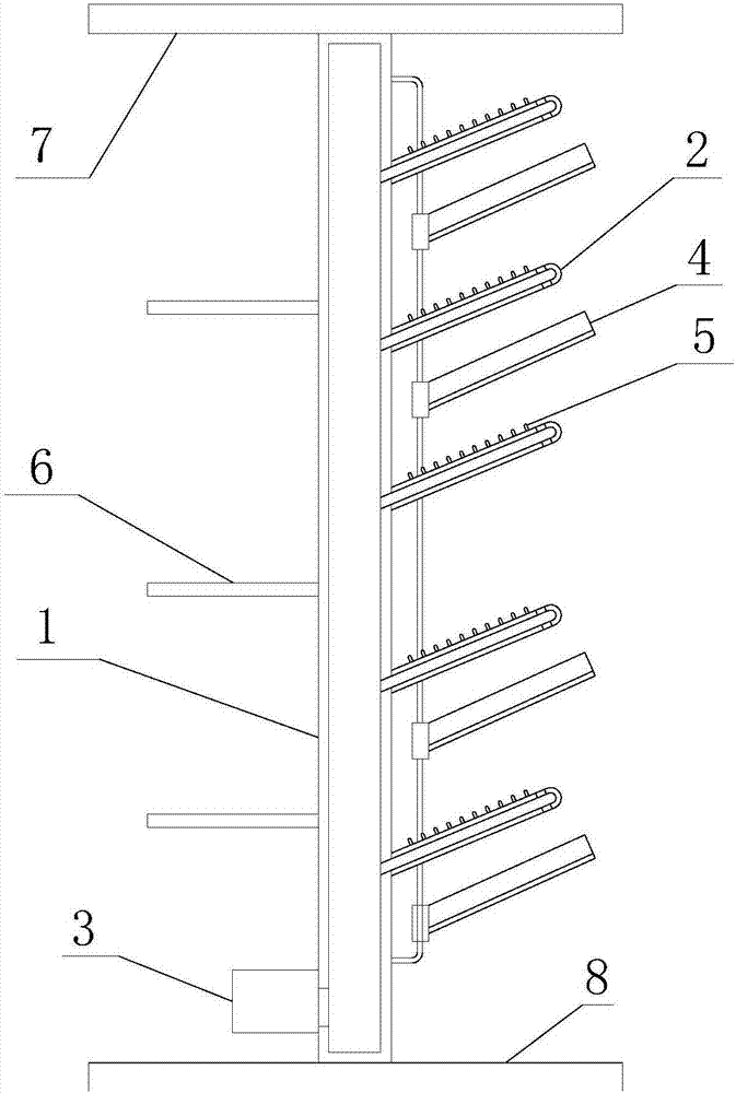
[0018] Such as figure 1 as shown, figure 1 It is a structural schematic diagram of an anti-collision air suction drip rack proposed by the present invention.

[0019] refer to figure 1 , a kind of anti-collision air suction drip stand proposed by the embodiment of the present invention, comprising: a board body 1 and a rod body 2 fixed to the board body 1 at one end, wherein:

[0020] There is a clamping cavity inside the plate body 1, the clamping cavity has an air port, and a negative pressure generator 3 is provided at the gas port, and the negative pressure generator 3 is used to generate negative pressure at the gas port; the height of the end of the rod body 2 away from the plate body 1 from the horizontal Larger than the end close to the plate body 1, the inside of the rod body 2 is provided with a linear cavity connected with the clamp cavity, and t...


PUM


Abstract

The invention discloses an anti-collision wind suction type water dripping frame, which comprises a plate body and a rod body, wherein one end of the rod body and the plate body are fixed, a clamping cavity is arranged in the plate body and is provided with a gas port, the gas port position is provided with a negative pressure generator, the negative pressure generator is used for generating a negative pressure at the gas port position, the height between the rod body end away from the plate body and the level is larger than the height between the rod body close to the plate body and the level, a linear cavity communicated to the clamping cavity is arranged in the rod body, one end positioned on the side wall of the rod body and away from the plate body is provided with a gas suction hole, and the gas suction hole is communicated to the linear cavity. According to the present invention, by arranging the clamping cavity in the plate body, arranging the linear cavity in the rod body, and arranging the negative pressure generator at the gas port position, the air can enter through the gas suction hole, can pass through the linear cavity and the clamping cavity, and then can be discharging through the gas port, such that the air can flow from the test tube member opening on the rod body to the interior so as to perform the air drying on the test tube member, and the test tube member cannot violently shake and collide.

Description

technical field [0001] The invention relates to the technical field of experimental equipment, in particular to an anti-collision air suction drip rack. Background technique [0002] The test tube is one of the most commonly used instruments in the laboratory. After the test tube is used, there will often be liquid inside. If it is not treated at this time, the accumulated water in the test tube may not be able to dry if it is time to use the test tube again, which will be harmful to the test tube again. Use will cause certain impact. In order to avoid this situation, the drip stand is often used at present, and the test tube is inserted on the rod of the drip stand. However, it will take a very long time for the water in the test tube to dry. Drying speed, the existing drip rack is provided with a blowing device to blow air to the inside of the test tube. Although the rod body of the drip rack with a blower device effectively speeds up the drying speed of the test tubes, s...

Claims


Application Information

Patent Timeline
Patent Type & Authority Applications(China)
IPC IPC(8): B01L9/06
CPCB01L9/06
Inventor 李钦才
Owner ANHUI DONGGUAN INSTR EQUIP
Why Eureka
Try Eureka