

Plate shearing machine
A plate shearing machine and plate cutting technology, applied in the field of plate processing, can solve problems such as high limitations, inability to change the size, and low shearing efficiency
- Summary
- Abstract
- Description
- Claims
- Application Information
AI Technical Summary
Problems solved by technology
Method used
Image

Examples
Embodiment Construction
[0021] Specific embodiments of the present invention will be described in detail below in conjunction with the accompanying drawings. It should be understood that the specific embodiments described here are only used to illustrate and explain the present invention, and are not intended to limit the present invention.
[0022] In the present invention, in the absence of a contrary statement, the orientation words included in the term such as "up, down, left, right, inside, outside" only represent the orientation of the term in the normal use state, or for the purpose of A common term understood by those skilled in the art, and should not be considered as a limitation of the term.
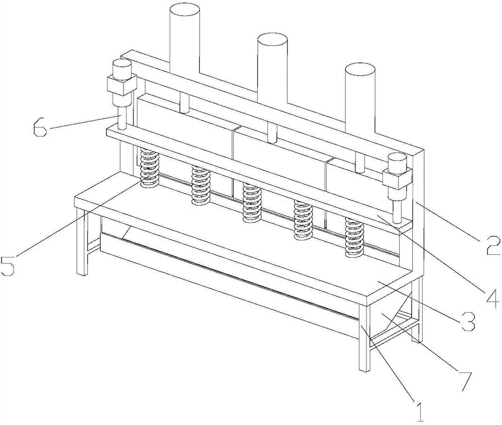
[0023] The invention provides a shearing machine, which comprises a support base 1, a support plate 3, a support frame body 2 and a plurality of plate cutting units; the support frame body 2 is fixedly connected to the support base 1 , two adjacent cutting board units are detachably connected to for...
PUM
 Abstract
Description
Claims
Application Information