Lifting support equipment of drilling fluid pipe manifold

A support equipment, lift-type technology, applied in drilling equipment, drill pipe, liquid/gas jet drilling, etc., can solve the problem that the drilling fluid manifold cannot be lifted and supported

Inactive Publication Date: 2017-09-15
JIANGSU HENGXIN PETROCHEM MACHINERY
View PDF0 Cites 0 Cited by
  • Summary
  • Abstract
  • Description
  • Claims
  • Application Information

AI Technical Summary

Problems solved by technology

[0005] Aiming at the deficiencies of the prior art, the present invention provides a lifting support device for the drilling fluid manifold, which has the advantages of lifting and supporting, and solves the problem that the drilling fluid manifold cannot be lifted and supported

Method used


Image

  • Lifting support equipment of drilling fluid pipe manifold
  • Lifting support equipment of drilling fluid pipe manifold
  • Lifting support equipment of drilling fluid pipe manifold

Examples


Embodiment Construction

[0022] The following will clearly and completely describe the technical solutions in the embodiments of the present invention with reference to the accompanying drawings in the embodiments of the present invention. Obviously, the described embodiments are only some, not all, embodiments of the present invention. Based on the embodiments of the present invention, all other embodiments obtained by persons of ordinary skill in the art without making creative efforts belong to the protection scope of the present invention.

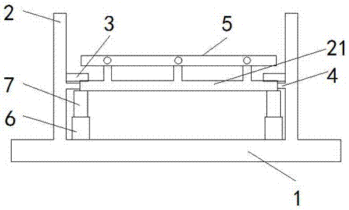
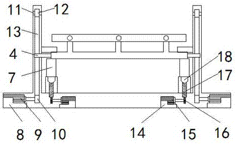
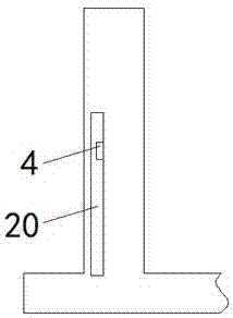
[0023] see Figure 1-4 , an elevating support device for a drilling fluid manifold, including a base 1, two support rods 2 are fixedly connected to both sides of the top of the base 1, and the inside of the support rod 2 and the inside of the base 1 are provided with interconnected spaces. Slot 19, the opposite side of the support rod 2 on both sides of the top of the base 1 is provided with a strip-shaped through hole 20 communicating with the empty groove 19...


PUM


Abstract

The invention relates to the technical field of drilling fluid manifolds, and discloses a lifting support device for drilling fluid manifolds, which includes a base, two support rods are fixedly connected to both sides of the top of the base, and the inside of the support rods The interior of the base and the base are provided with interconnected empty slots, the opposite sides of the support rods on both sides of the top of the base are provided with strip-shaped through holes connected to the empty slots, and the opposite sides of the support rods on both sides of the top of the base are fixed Blocks are connected, and first support columns are fixedly connected to both sides of the top of the base. The lifting support equipment of the drilling fluid manifold, through the device of the first motor, the rotating shaft, the conveyor belt and the connecting rod, the first motor can rotate the rotating shaft after the normal operation and drive the push belt to rotate, so that the push belt on the The connecting rod then moves upwards, so that the manifold at the end of the connecting rod away from the support rod is lifted upwards, and then the drilling fluid manifold is lifted upwards.

Description

technical field [0001] The invention relates to the technical field of drilling fluid manifolds, in particular to a lifting support device for drilling fluid manifolds. Background technique [0002] Drilling fluid manifold is one of the main equipment of high-pressure jet drilling. It collects the mud discharged by two mud pumps. Through the control of high-pressure valve group, the high-pressure mud excitation liquid is input into the inner wall of the drill pipe and ejected from the drill bit to generate high-pressure mud flow. Realize high-pressure jet drilling. Using this product can significantly increase the drilling speed and reduce the drilling cost. The drilling fluid manifold is composed of mud gate valves, high-pressure unions, tees, crosses, elbows, high-pressure hoses, pup joints, pressure gauges, etc. , The ground valve group adopts goose-shaped three-way structure, which has the characteristics of compact structure, small fluid resistance, and can give full pl...

Claims


Application Information

Patent Timeline
Patent Type & Authority Applications(China)
IPC IPC(8): E21B21/00E21B19/00E21B7/18
CPCE21B21/00E21B7/18E21B19/00
Inventor 薛山袁志国薛友恒秦永爽
Owner JIANGSU HENGXIN PETROCHEM MACHINERY
Why Eureka
Try Eureka