Laser radar two-step calibration method based on calibration field

A technology of laser radar and calibration method, applied in radio wave measurement systems, instruments, etc., can solve problems such as difficulty in ensuring calibration accuracy

Active Publication Date: 2017-09-15
BEIJING INST OF CONTROL ENG
View PDF5 Cites 31 Cited by
  • Summary
  • Abstract
  • Description
  • Claims
  • Application Information

AI Technical Summary

Problems solved by technology

[0003] In the prior art, conventional methods mostly use a flat plate with better flatness and use planar features to constrain lidar calibration. On the one hand, the above method has high design and processing requirements for the calibration device; on the other hand, although it can be

Method used


Image

  • Laser radar two-step calibration method based on calibration field
  • Laser radar two-step calibration method based on calibration field
  • Laser radar two-step calibration method based on calibration field

Examples


Embodiment Construction

[0098] In order to make the technical scheme of the present invention clearer, the present invention will be further described below in conjunction with description of drawings and specific embodiments:

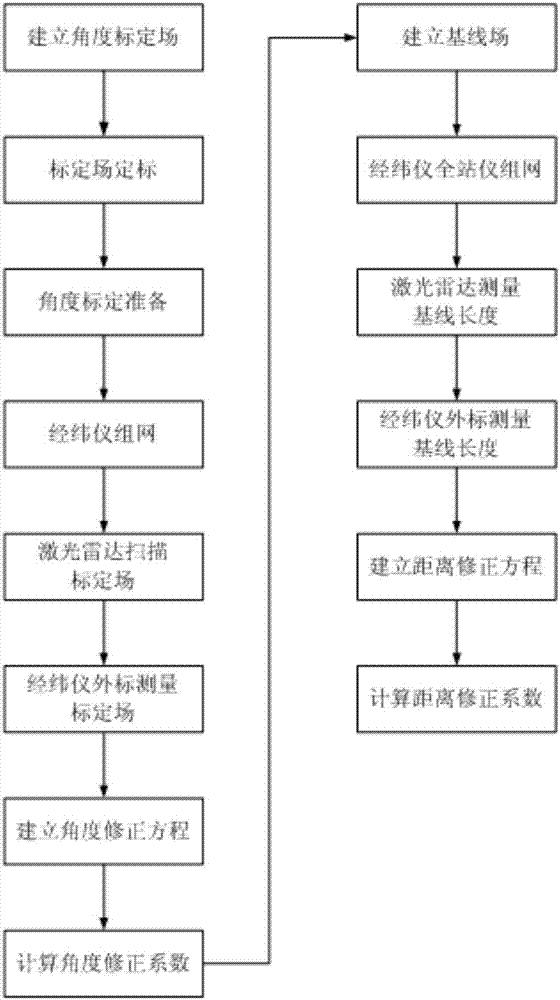
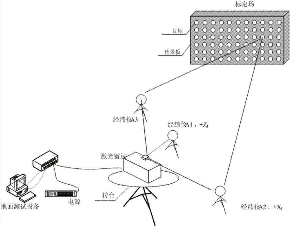
[0099] Such as Figure 1~3 As shown, a two-step calibration method for lidar based on the calibration field includes the following steps:

[0100] Step 1: Arrange N reflective targets on the black background board to establish the lidar angle calibration field;

[0101] Step 2: Use the photogrammetry camera to calibrate the lidar angle calibration field, and measure the positions of the geometric centers of N reflective targets in the body coordinate system of the lidar angle calibration field, and set the corresponding coordinate values ​​to (X Ci , Y Ci ,Z Ci );

[0102] Step 3: Install the laser radar on the turntable, set the initial scanning range of the laser radar and the angle of the turntable, and place the laser radar angle calibration field in the light emittin...


PUM


Abstract

The invention discloses a laser radar two-step calibration method based on a calibration field. The method comprises steps of establishing a calibration field; carrying out calibration; preparing angle calibration; networking a theodolite; scanning a laser radar; measuring the theodolite; establishing an angle correction equation; calculating an angle correction coefficient; establishing a base line field; measuring the laser radar; measuring the theodolite; establishing a distance correction equation; and calculating a distance correction coefficient. According to the invention, rapid calibration of the laser radar is achieved without taking a precisely designed and processed calibration device as a calibration standard; a problem of too high requirements on a test place, the calibration field and the calibration device in the normal method is solved; through cooperation of a rotation bench, the whole test process is achieved, the test difficulty level is reduced and a difficulty in ensuring precision of full field-of-view angle correction in the normal method is solved; and through the test of the calibration field and the base line field step by step, effects of correcting separation distances in a calibration model are achieved and disadvantages in mutual coupling of distance parameters and angle parameters in the normal method are overcome.

Description

technical field [0001] The invention relates to a laser radar calibration method, which belongs to the technical field of imaging sensor calibration. Background technique [0002] Lidar is a new type of laser measurement sensor used for target acquisition, distance and angle measurement, position and attitude measurement, and three-dimensional reconstruction of space non-cooperative targets. In order to ensure the successful acquisition probability of the laser radar to the non-cooperative target, the sensor is required to have a high angle measurement accuracy in the whole measurement range. Therefore, how to correct the angle measurement and ranging errors of the lidar with high precision and determine the position and attitude of the lidar measurement system is the premise of realizing the high-precision measurement of the sensor, and it is also a problem to be solved in the calibration of the lidar. [0003] In the prior art, conventional methods mostly use a flat plate...

Claims


Application Information

Patent Timeline
IPC IPC(8): G01S7/497
CPCG01S7/497
Inventor 吴奋陟王立郭绍刚朱飞虎吴云刘达
Owner BEIJING INST OF CONTROL ENG
Why Eureka
Try Eureka