Eureka AIR delivers breakthrough ideas for toughest innovation challenges, trusted by R&D personnel around the world.

Touch control display panel and touch control display device

A touch display panel, touch electrode technology, applied in the direction of instruments, computing, electrical digital data processing, etc., can solve the problem of capacitive effect, reduce the signal strength of the touch signal line, affect the normal operation of the touch electrode, etc. To achieve the effect of avoiding the capacitance effect

Inactive Publication Date: 2017-09-19
SHANGHAI AVIC OPTOELECTRONICS
View PDF8 Cites 11 Cited by
  • Summary
  • Abstract
  • Description
  • Claims
  • Application Information

AI Technical Summary

Problems solved by technology

However, the electrical signal on the touch signal line is usually different from the electrical signal on other touch electrodes, resulting in a potential difference between the touch signal line and the passing touch electrode, resulting in a capacitive effect.
The capacitive effect interferes with the signal on the touch signal line, which may reduce the strength of the signal on the touch signal line, which in turn will affect the normal operation of the touch electrode

Method used


Image

  • Touch control display panel and touch control display device
  • Touch control display panel and touch control display device
  • Touch control display panel and touch control display device

Examples


Embodiment Construction

[0031] The application will be further described in detail below in conjunction with the accompanying drawings and embodiments. It should be understood that the specific embodiments described here are only used to explain related inventions, rather than to limit the invention. It should also be noted that, for the convenience of description, only the parts related to the related invention are shown in the drawings.

[0032] It should be noted that, in the case of no conflict, the embodiments in the present application and the features in the embodiments can be combined with each other. The present application will be described in detail below with reference to the accompanying drawings and embodiments.

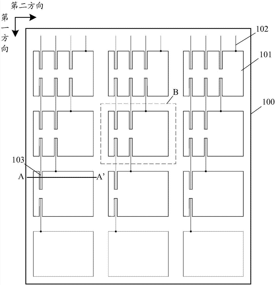
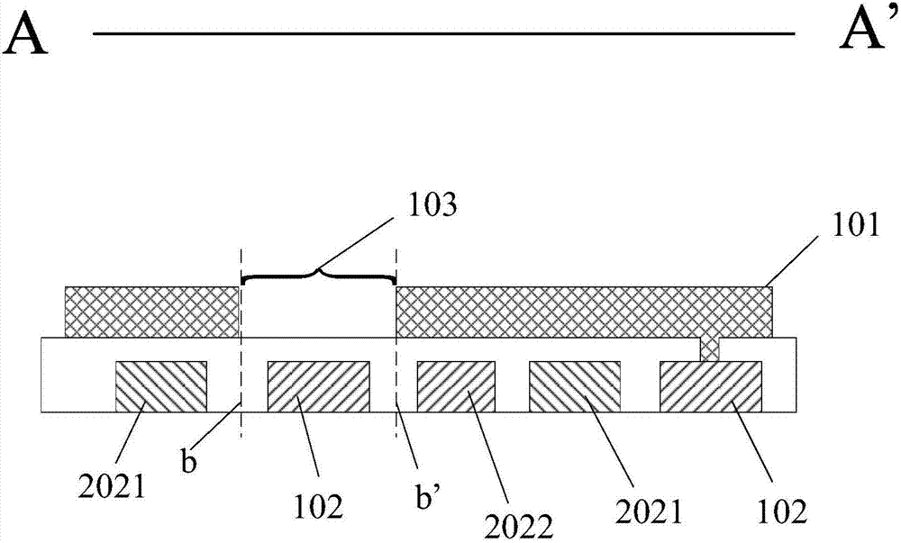
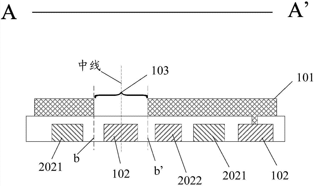
[0033] The touch display panel includes an array substrate and a color filter substrate, and the array substrate and the color filter substrate are aligned and bonded by a frame sealant. The second glass substrate of the color filter substrate is slightly larger to form a st...


PUM


Abstract

The application discloses a touch control display panel and a touch control display device. The touch control display panel comprises a first electrode layer, a first metal layer and a second electrode layer, wherein a plurality of touch control electrodes in array arrangement are arranged on the first electrode layer; a plurality of touch control signal wires are arranged on the first metal layer, each touch control signal wire is electrically connected with a touch control electrode, and each touch control electrode is at least electrically connected with one touch control signal wire; a plurality of pixel electrodes in array arrangement are arranged on the second electrode layer; incised slots are arranged between the touch control signal wires and the touch control electrodes that are insulated from each other, the projection boundary of the incised slots in the direction perpendicular to the touch control display panel is positioned between the touch control signal wires and the pixel electrodes. In the above touch control panel and touch control display device, incised slots are formed in the touch control electrodes, which can avoid the capacity effect generated due to different electric potentials of the touch control signal wires and the touch control electrodes that are insulated with each other, and can prevent the electromagnetic signals of the touch control signal wires from passing through the touch control electrodes to radiate out.

Description

technical field [0001] The present application relates to the field of display technology, in particular to the field of organic light-emitting display technology, and in particular to a touch display panel and a touch display device. Background technique [0002] With the continuous improvement of the application field and technology of touch display technology, more touch electrodes can be arranged on the array substrate of the touch display panel, and more touch sensing electrodes can be arranged on the color filter substrate to improve the touch control. The accuracy with which the display senses touch signals. [0003] The more touch sensing electrodes per unit area, the more touch signal lines connected to the touch electrodes. Since the touch electrodes are arranged in an array, most touch signal lines need to pass through other touch electrodes before being electrically connected to the corresponding touch electrodes. However, the electrical signal on the touch sig...

Claims


Application Information

Patent Timeline
Patent Type & Authority Applications(China)
IPC IPC(8): G02F1/1333G02F1/1343G06F3/041
CPCG02F1/13338G02F1/1343G06F3/0412
Inventor 王听海曹兆铿秦丹丹
Owner SHANGHAI AVIC OPTOELECTRONICS
Why Eureka
Eureka Blog
Learn More