Fuel cell system and method for operating a fuel cell system

A fuel cell system, fuel cell stack technology, applied in battery/battery traction, fuel cell, fuel cell control, etc. Improve efficiency and save energy

Active Publication Date: 2017-09-19
VOLKSWAGEN AG +1
View PDF9 Cites 7 Cited by
  • Summary
  • Abstract
  • Description
  • Claims
  • Application Information

AI Technical Summary

Problems solved by technology

However, especially when the fuel cell system is arranged in a vehicle, such complex control methods often lead to undesired effects and overall reduced dynamics and overall reduced efficiency

Method used


Image

  • Fuel cell system and method for operating a fuel cell system
  • Fuel cell system and method for operating a fuel cell system
  • Fuel cell system and method for operating a fuel cell system

Examples


Embodiment Construction

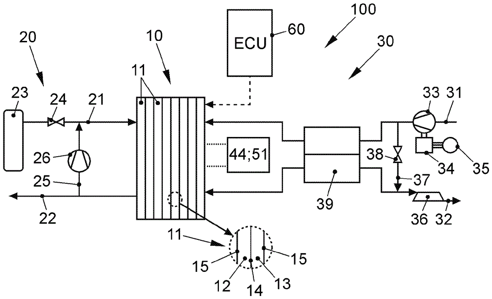
[0043] figure 1 A fuel cell system designated as a whole by 100 according to a preferred embodiment of the invention is shown. The fuel cell system 100 is part of a vehicle, not further shown, in particular an electric vehicle, which has an electric traction motor that is supplied with electrical energy by a corresponding fuel cell system 100 .

[0044] The fuel cell system 100 includes a fuel cell stack 10 as a core component, the fuel cell stack 10 has a plurality of single cells 11 arranged in a stack shape, and the single cells 11 pass through alternately stacked membrane electrode assemblies (MEAs) 14 plate 15 (see detail fragment). Each individual cell 11 therefore comprises an MEA 14 in each case which has an ion-conducting polymer electrolyte membrane (not shown further here) and catalytic electrodes arranged on both sides of the polymer electrolyte membrane. These electrodes catalyze the corresponding sub-reactions of fuel conversion. The anode and cathode electrod...


PUM


Abstract

The disclosure relates to a fuel cell system and a method for controlling the fuel cell system (100) comprising a fuel cell stack (10) for providing an electrical power Pstack depending on a power demand, at least one auxiliary unit (24, 26, 33, 34, 38) for operating the fuel cell stack (10) with an electrical power consumption Paux, at least one consumer (44, 51) with an electrical power request Puse, and a control unit (60) for regulating the power demand as well as a method for controlling such a fuel cell system. It is provided that the control unit (60) is configured to selectively operate the fuel cell system (100) in a first operating mode or in a second operating mode, whereby the fuel cell stack (10) is turned off depending on the operating mode upon the falling below of an optimal efficiency degree operating point P(Eta max) of the fuel cell system (100) or a minimum operating point Pmin of the fuel cell stack. In particular, at least one auxiliary unit (24, 26, 33, 34, 38) is also turned off in the first operating mode, when the optimal efficiency degree operating point decreases.

Description

technical field [0001] The invention relates to a fuel cell system and a method for operating a fuel cell system. Furthermore, the invention relates to a vehicle with such a fuel cell system. Background technique [0002] Fuel cells use the chemical reaction of fuel and oxygen to produce water in order to generate electricity. For this purpose, the fuel cell contains, as a core component, a so-called membrane electrode assembly (MEA stands for: membrane electrode assembly), which consists of an ion-conducting (mostly proton-conducting) membrane and each a A structure consisting of catalytic electrodes (anode and cathode) arranged on both sides of the membrane. Typically, a fuel cell is formed of a plurality of MEAs arranged in a stack, the electrical power of which is summed. Between the individual membrane electrode assemblies bipolar plates (also referred to as flow field plates or separator plates) are usually arranged, which ensure the supply of the operating medium, ...

Claims


Application Information

Patent Timeline
Patent Type & Authority Applications(China)
IPC IPC(8): H01M8/04228H01M8/04303
CPCH01M8/04H01M8/04298H01M2250/20H01M8/04947H01M8/04604H01M8/04619H01M8/04626B60L50/72H01M8/0494H01M16/006H01M2008/1095Y02T90/40Y02E60/50Y02E60/10
Inventor A.韦斯M.迪韦尔H.施勒德
Owner VOLKSWAGEN AG
Why Eureka
Try Eureka