Switching device and method for running the switching device and motor vehicle electrical system

A technology for switching devices and electrical appliances, which is applied in the field of power switching devices and operates such switching devices, which can solve the problems of reducing the stability of parallel circuits and exacerbating the risk of localization/filament damage of power switches, so as to reduce power loss, Effect of reducing conduction loss

Active Publication Date: 2018-07-27
ROBERT BOSCH GMBH
View PDF12 Cites 0 Cited by
  • Summary
  • Abstract
  • Description
  • Claims
  • Application Information

AI Technical Summary

Problems solved by technology

However, a lower gate-source voltage aggravates the localization / filamentization of the current in the power switch and increases the risk of damage, since the resulting power losses are no longer distributed over the entire surface of the power switch and can therefore be lost in the power switch. A point-by-point overload is generated inside the switch ( )
[0006] In modern power switches, therefore, not only the reduced chip area (due to improved performance) is disadvantageous, but additionally the stability in parallel circuits due to the reduced gate-source voltage (at the same operating point) Lowering is also bad

Method used


Image

  • Switching device and method for running the switching device and motor vehicle electrical system
  • Switching device and method for running the switching device and motor vehicle electrical system
  • Switching device and method for running the switching device and motor vehicle electrical system

Examples


Embodiment Construction

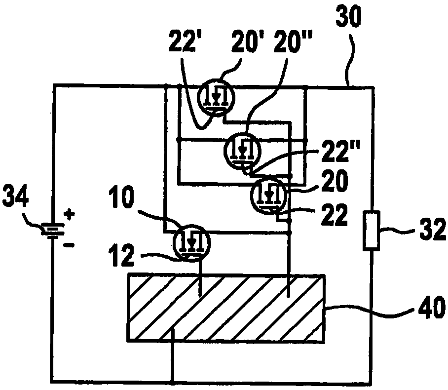
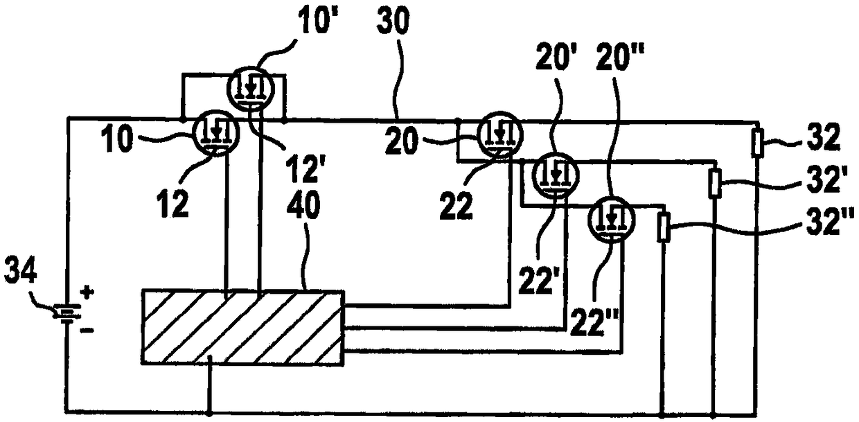
[0037] exist figure 1 A schematic diagram of the circuit of a first embodiment of the switching device according to the invention is shown in . The consumer 32 is connected to a battery 34 of the vehicle electrical system 48 via a consumer circuit 30 . The consumer current loop 30 can be switched on and off via the first power switch 10 and the second power switch 20 . In this case, the first power switch 10 and the second power switch 20 are arranged in parallel with one another. In addition to the second power switch 20, there are two further second power switches 20', 20", wherein the second power switches 20, 20', 20" are connected to one another in such a way that when the consumer current circuit is switched on In this case, the total current is distributed to all second power switches 20, 20', 20".

[0038] The first power switch 10 and the second power switch 20 , 20 ′, 20 ″ are switched on and off by the device 40 for control. Preferably, the device 40 for control...


PUM


Abstract

A switching device is described, which includes a first power switch (10) having first minimum on resistance RDS(on), a second power switch (20) having second minimum on resistance R'DS(on), the firstpower switch (10) and the second power switch (20) being configured to be used for switching on and off a whole electric appliance current loop (30), and a device (40) for control configured to be used for switching on and off the first power switch (10) and the second power switch (20) independently of each other, the first minimum on resistance RDS(on) exceeding second minimum on resistance R'DS(on) by at least 10%. A method for running the switching device is also provided, and the method includes switching on and off the first power switch (10), and switching on and off the second power switch (20) under control of a threshold value.

Description

technical field [0001] The invention relates to a switching device, preferably a semiconductor-based power switch arrangement, and a method for operating such a switching device. In particular, the invention relates to a device for operating power switches on sensitive power supply networks. Background technique [0002] In modern vehicles, supply networks with voltages higher than 12 V are increasingly installed. An example is the 48 V vehicle electrical system, which will be increasingly used in the future due to the continuously increasing number of electrical consumers, the significantly higher power requirements and a number of other reasons. Compared with the 12V or 24V vehicle electrical network mainly used today, the error tolerance of this electrical network is significantly smaller. In particular, possible overvoltages can hardly be tolerated any longer in the 48 V vehicle electrical system. Such overvoltages occur in particular during switch-on and switch-off o...

Claims


Application Information

Patent Timeline
Patent Type & Authority Applications(China)
IPC IPC(8): H03K17/16H03K17/284H03K17/30H03K17/687H03K4/06
CPCH03K4/06H03K17/16H03K17/284H03K17/30H03K17/687H03K17/164
Inventor W·席曼J·朱斯
Owner ROBERT BOSCH GMBH
Why Eureka
Try Eureka