Non-isolated grid-connected inverter and switch control time sequence thereof
An inverter, non-isolated technology, applied in the field of non-isolated photovoltaic grid-connected inverters, to achieve the effects of improving efficiency, reducing conduction loss, and suppressing leakage current
Inactive Publication Date: 2010-08-25
NANJING UNIV OF AERONAUTICS & ASTRONAUTICS
View PDF0 Cites 43 Cited by
- Summary
- Abstract
- Description
- Claims
- Application Information
AI Technical Summary
Problems solved by technology
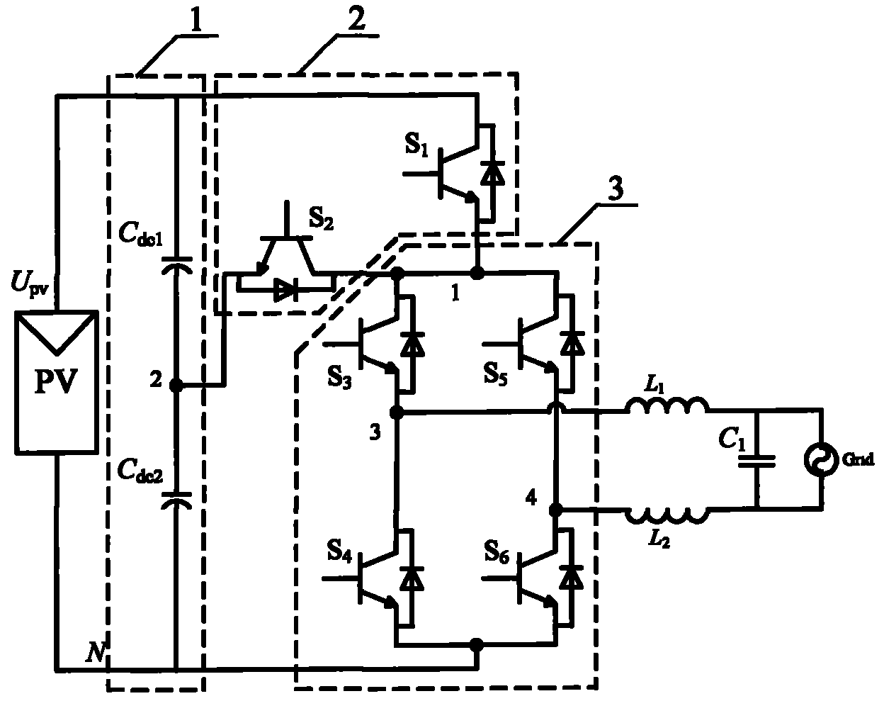
However, according to the high-frequency common-mode equivalent model of the full-bridge circuit, in order to eliminate the high-frequency common-mode voltage generated by unipolar SPWM modulation, the potential of the freewheeling circuit in the freewheeling stage must be clamped at half of the input voltage of the solar cell, so that Complete elimination of common-mode voltages rather than simply disconnecting the panels from the grid
Method used
View moreImage
Smart ImageViewing Examples
Examples
specific example
Login to View More PUM
 Abstract
The invention provides a non-isolated grid-connected inverter and a switch control time sequence thereof. The non-isolated grid-connected inverter comprises a voltage dividing capacitor branch (1), a clamping branch (2) and a full-bridge basic unit (3), wherein the voltage dividing capacitor branch (1) consists of a first voltage dividing capacitor (Cdc1) and a second voltage dividing capacitor (Cdc2), the clamping branch (2) consists of a first power switch pipe (S1) and a second power switch pipe (S2), and the full-bridge basic unit (3) consists of a third power switch pipe (S3), a fourth power switch pipe (S4), a fifth power switch pipe (S5) and a six power switch pipe (S6). The invention adds two controllable switch pipes and voltage dividing capacitors on the basis of a full-bridge circuit for forming a bidirectional clamping branch, is matched with the switch time sequence, and can realize the battery voltage at a half of the follow current loop potential in the follow current stage, so the leakage current of the non-isolated grid-connected inverter is eliminated, the output current only passes through three switch pipes in the power transmission stage is ensured, and the conduction consumption is effectively reduced.
Description
technical field The invention relates to a non-isolated photovoltaic grid-connected inverter, which belongs to the topology of a grid-connected inverter. Background technique Non-isolated photovoltaic grid-connected inverters have the advantages of high efficiency, small size, light weight and low cost. However, due to the existence of the parasitic capacitance of the solar panel to the ground, the switching action of the switching device of the grid-connected inverter may generate a high-frequency time-varying voltage to act on the parasitic capacitance, and the leakage current induced by this may exceed the allowable range. The generation of high-frequency leakage current will bring conduction and radiation interference, increase the harmonics and loss of the incoming current, and even endanger the safety of equipment and personnel. The unipolar SPWM full-bridge grid-connected inverter has excellent differential mode characteristics, such as high utilization rate of inpu...
Claims
Login to View More Application Information
Patent Timeline
 Patent Type & Authority Applications(China)
IPC IPC(8): H02M7/53H02N6/00
CPCH02M2001/007Y02E10/56H02M7/5388H02M2001/123H02M1/007H02M1/123
Inventor 肖华锋谢少军杨晨
Owner NANJING UNIV OF AERONAUTICS & ASTRONAUTICS
Features
- R&D
- Intellectual Property
- Life Sciences
- Materials
- Tech Scout
- Unparalleled Data Quality
- Higher Quality Content
- 60% Fewer Hallucinations
Learn More Browse by: Latest US Patents, China's latest patents, Technical Efficacy Thesaurus, Application Domain, Technology Topic, Popular Technical Reports.
© 2025 PatSnap. All rights reserved.Legal|Privacy policy|Modern Slavery Act Transparency Statement|Sitemap|About US| Contact US: help@patsnap.com


