Method for Controlling Bidirectional DC-DC Converter

Inactive Publication Date: 2008-03-27
TOYOTA IND CORP
View PDF3 Cites 47 Cited by
  • Summary
  • Abstract
  • Description
  • Claims
  • Application Information

AI Technical Summary

Benefits of technology

[0011] It is an object of the present invention to provide a method for controlling a bidirectional DC-DC converter capable of reducing switching loss d

Problems solved by technology

This may prolong the duration of the dead time.
Since the duration of the dead time varies in accordance with the voltage conditions,

Method used


Image

  • Method for Controlling Bidirectional DC-DC Converter
  • Method for Controlling Bidirectional DC-DC Converter
  • Method for Controlling Bidirectional DC-DC Converter

Examples


Embodiment Construction

[0033] A method for controlling a bidirectional DC-DC converter 10 according to a preferred embodiment of the present invention will now be described in detail with reference to FIGS. 1 to 18.

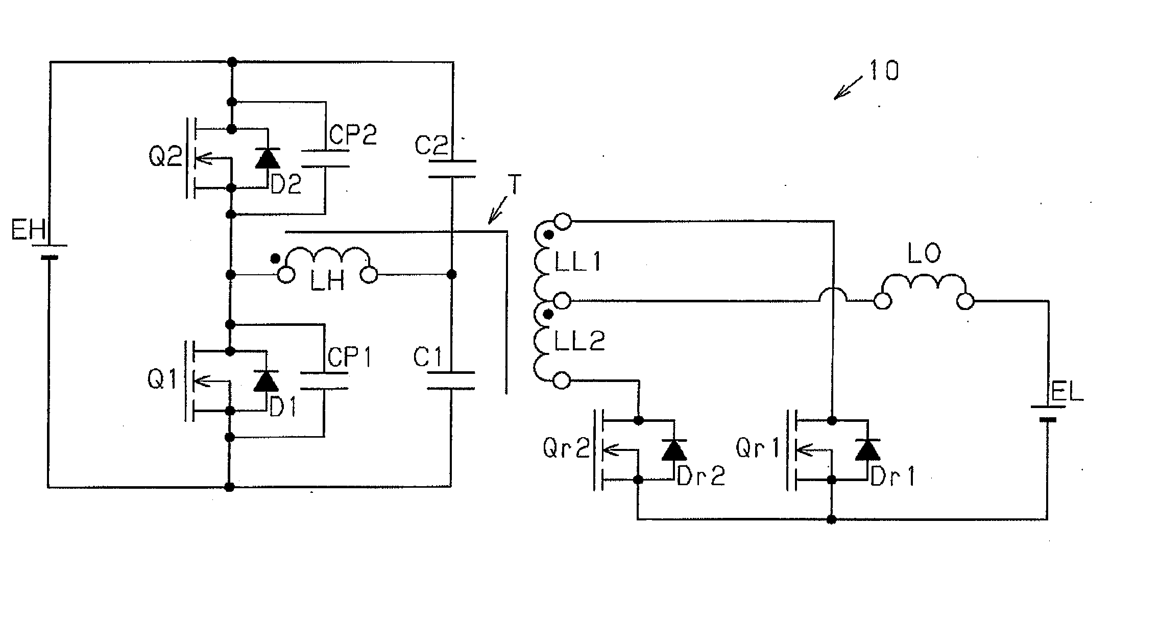
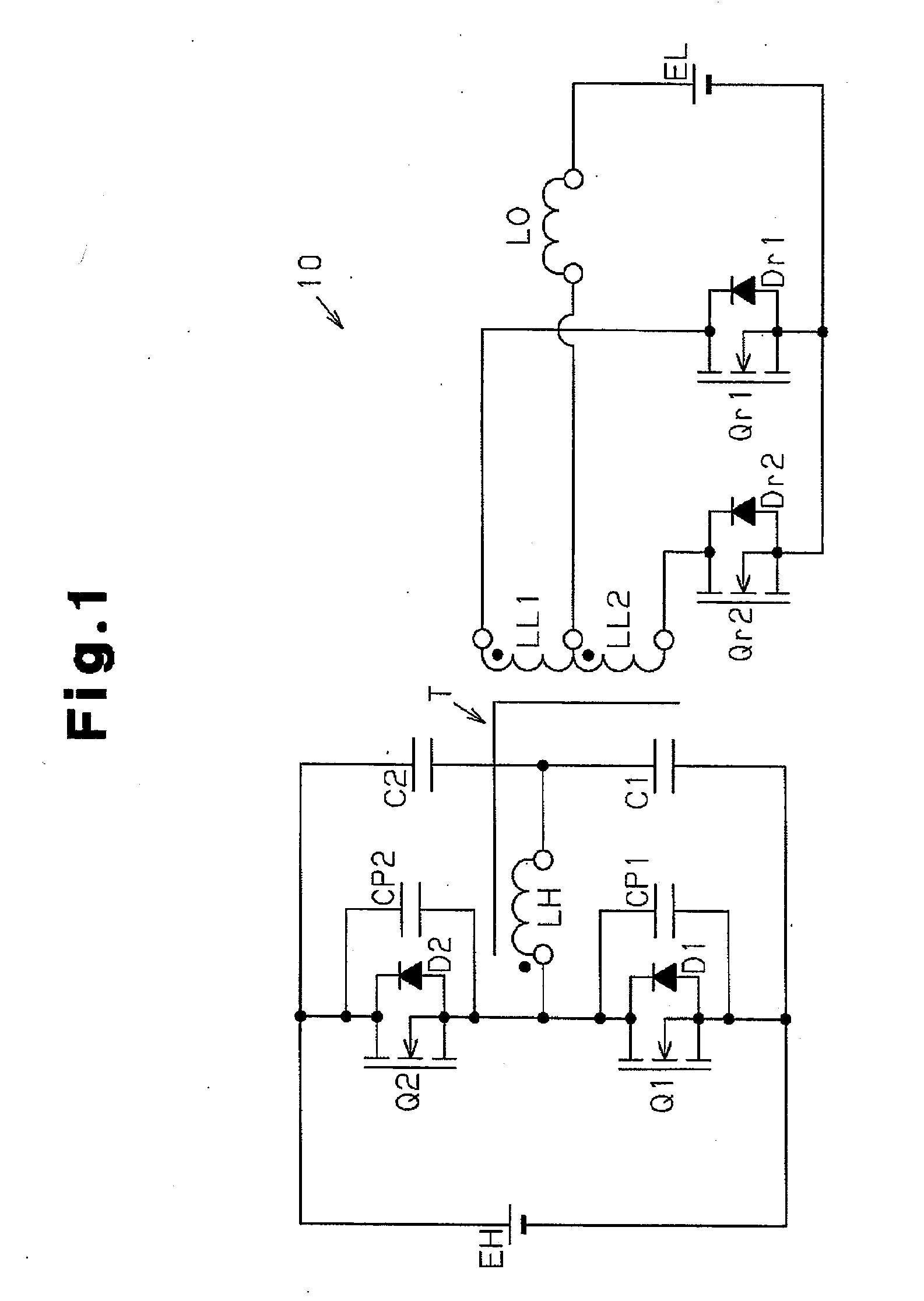
[0034]FIG. 1 is a schematic circuit diagram of the bidirectional DC-DC converter 10. The illustrated bidirectional DC-DC converter 10 enables bidirectional power transmission. In other words, the DC-DC converter 10 selectively executes a step-down operation for transmitting power from a high voltage EH to a low voltage EL via a transformer T and a step-up operation for transmitting power from the low voltage EL to the high voltage EH via the transformer T.

[0035] The bidirectional DC-DC converter 10 has the following configuration. A reference terminal (terminal marked by black dot in FIG. 1) of a high-voltage side winding LH of the transformer T is connected to a drain terminal of a MOS transistor Q1 and a source terminal of a MOS transistor Q2. A non-reference terminal of the high-voltage si...


PUM


Abstract

A method for controlling a bidirectional DC-DC converter that reduces switching loss during a step-down operation and conduction loss caused by synchronous rectification, while enabling bidirectional operation with the same control. The DC-DC converter includes first and second switch elements for alternately applying voltage in opposite directions to a transformer winding during the step-down operation and performing synchronous rectification during a step-up operation. Third and fourth switch elements perform synchronous rectification during the step-down operation and alternately apply voltage in opposite directions to the transformer in the step-up operation. The method includes activating the first switch when the third switch is in an active state, activating the second switch when the fourth switch is in an active state, switching each of the third and forth switches between an active state and an inactive state while inactivating the third or fourth switch.

Description

CROSS-REFERENCE TO RELATED APPLICATIONS [0001] This application is based upon and claims the benefit of priority from the prior Japanese Patent Application No. 2006-257229, filed on Sep. 22, 2006, the entire contents of which are incorporated herein by reference. FIELD OF THE INVENTION [0002] The present invention relates to a method for controlling a bidirectional DC-DC converter, and more particularly, to a method for controlling a bidirectional DC-DC converter capable of reducing switching loss and conduction loss through execution of a simple switching control. BACKGROUND OF THE INVENTION [0003]“Bidirectional DC-DC Converter for Super Capacitor-Based Energy Storage Systems” by Tomokazu Mishima et al., The Institute of Electronics, Information and Communication Engineers Technical Report of IEICE, EE2005-35 (2005-9), P. 19-24 (hereinafter referred to as “non-patent document 1”) discloses a bidirectional DC-DC converter. [0004] The bidirectional DC-DC converter disclosed in non-pa...

Claims


Application Information

Patent Timeline
IPC IPC(8): H02M3/335
CPCH02M3/33584
Inventor MOISEEV, SERGEYHIRABAYASHI, NOBUO
Owner TOYOTA IND CORP
Why Eureka
Try Eureka