Electrical Equipment

A technology for equipment and locking components, applied in electrical components, circuits, resistors, etc., can solve problems such as slow triggering, and achieve the effect of reducing friction and comprehensive decoupling

Active Publication Date: 2020-06-05
デーンエスエープルスツェオーカーゲー
View PDF8 Cites 0 Cited by
  • Summary
  • Abstract
  • Description
  • Claims
  • Application Information

AI Technical Summary

Problems solved by technology

This can result in "slow triggering" of the disconnection device before the associated thermal overload occurs

Method used


Image

  • Electrical Equipment
  • Electrical Equipment
  • Electrical Equipment

Examples


Embodiment Construction

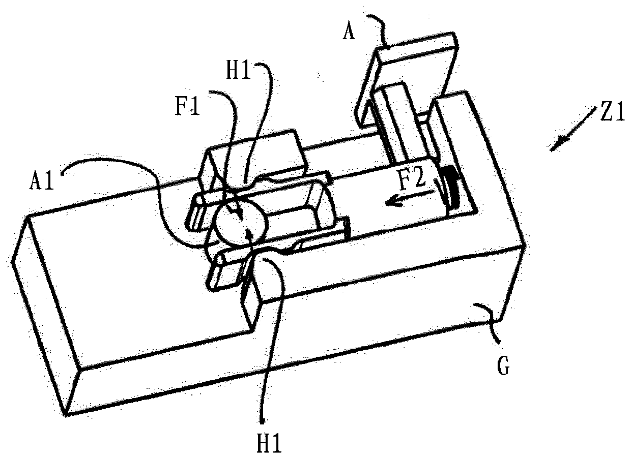
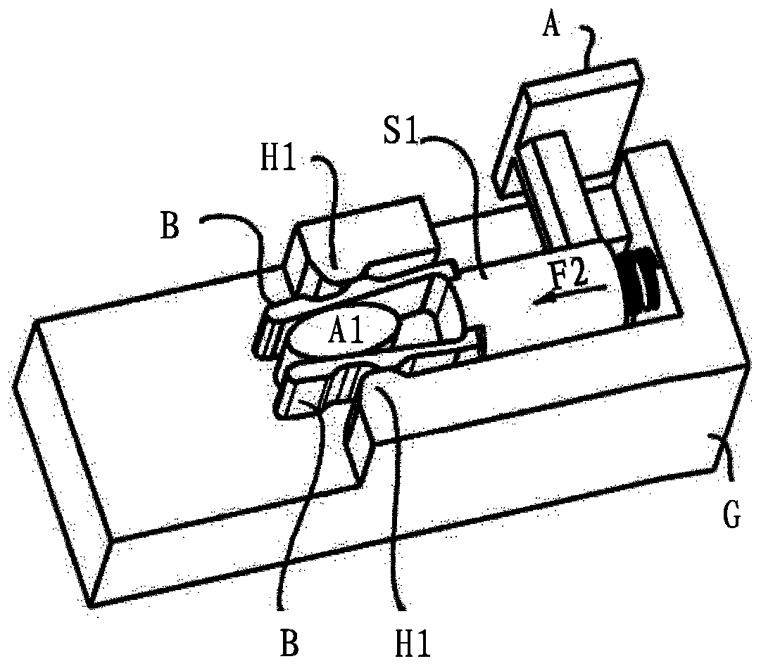
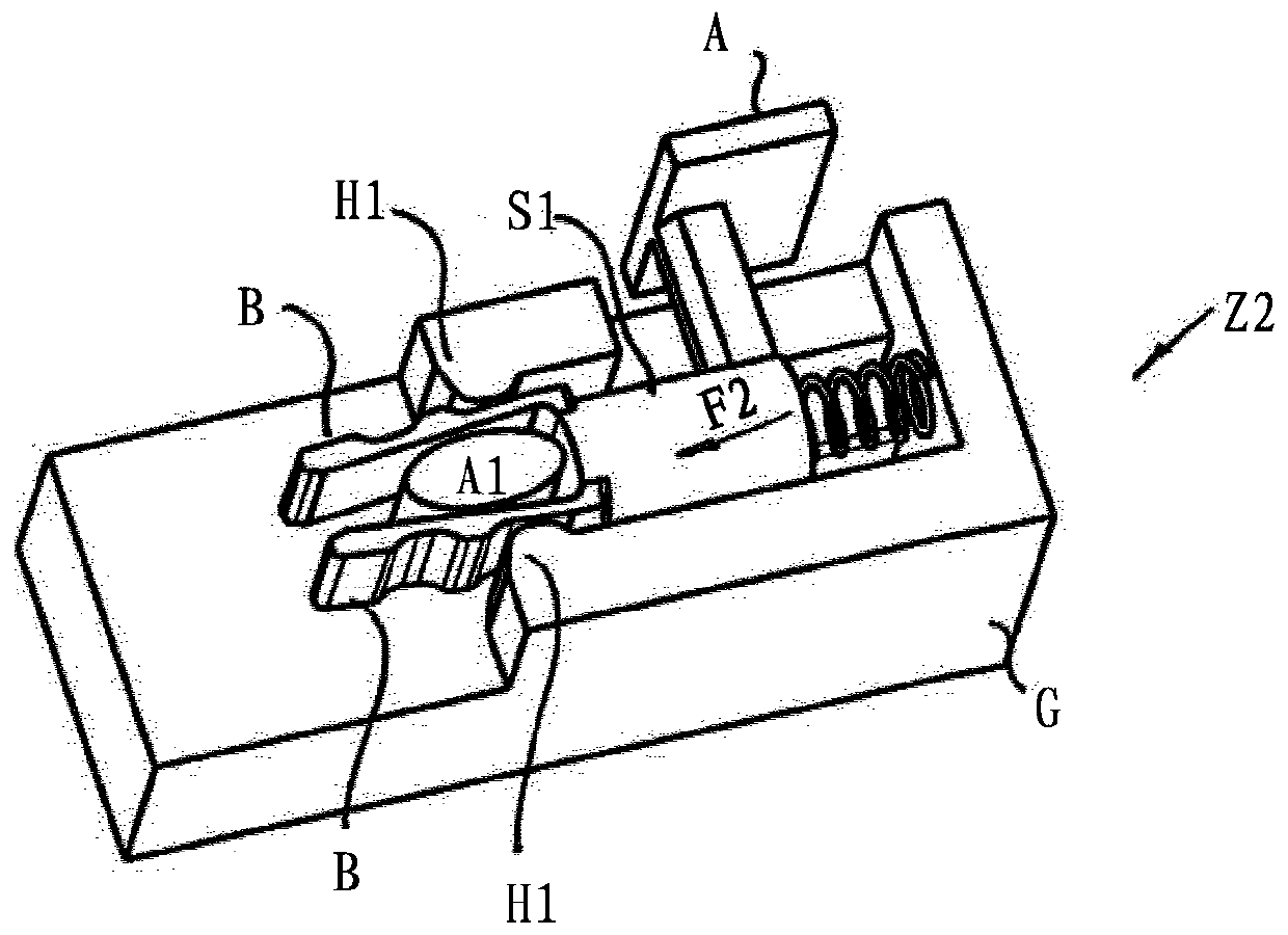
[0029] figure 1The device for thermally triggering or disconnecting the surge protector is shown in a first state Z1 , which device includes a display surface and a slider S1 . A second force F2 is applied to the slide by means of a helical spring. For this purpose, the helical spring supports the housing G in which the slide S1 is mounted. In this case, a helical spring acts as an energy store, wherein the second force F2 is correspondingly high, causing the slide S1 to move. The slide S1 has a holding device, which is realized by two opposing jaws B.

[0030] Furthermore, a locking element A1 is provided on the housing G. The locking element A1 is preferably in thermal contact with a heat source, in particular the surge protector, and is inserted loosely and held only by the jaw B.

[0031] The jaws B of the holding device are designed to be flexible, in particular made of a flexible plastic material. Furthermore, the jaw plates B each have an outwardly directed groove....


PUM


Abstract

The invention relates to a device for thermally triggering, disconnecting and / or signaling the state of a varistor, comprising a locking element on which a first force acts and which Change its aggregated state and / or change its external structure when the extreme temperature is exceeded. In addition, a slide is provided, which is locked by the locking element in the first state and on which a second force acts, so that the slide is locked when the locking element changes its state of assembly and / or its outer configuration. Transition into the second state, in which the lock and hold connected to the slider act clampingly on the locking element, via which the lock and hold indirectly locks the slide, and the second force is exerted by the The above-mentioned stop and hold device is decomposed into force components. Furthermore, the retaining device has at least one elastic, flexible jaw which, in the first state, bears against the locking element and against the surroundings of the slide, wherein the first A force corresponds to the force component.

Description

technical field [0001] The invention relates to a device for thermally triggering, disconnecting and / or signaling the state of a varistor, comprising a locking element on which a first force acts and which Changes its aggregated state and / or its external structure when the extreme temperature is exceeded. Background technique [0002] DE 10 2006 037 551 B4 shows a locking disconnection device, in which a movable welded profile is stressed by a pretensioned spring, but cannot be displaced as long as the welded pin blocks the movement path. If the welding pin melts due to a thermal overload, for example caused by a high current, the weld profile and thus the slide moves, so that for example an electrical circuit which outputs a warning signal is closed. [0003] DE 10 2010 061 110 A1 also discloses a thermal disconnection device, in which the first conductor section and the second conductor section are electrically coupled via thermally detachable contacts. At high temperatu...

Claims


Application Information

Patent Timeline
Patent Type & Authority Patents(China)
IPC IPC(8): H01H37/46H01H73/22H01C7/12
CPCH01C7/126H01H37/323H01H37/46H01H71/18H01T1/14H01H73/22
Inventor U·施特朗费尔德S·希尔
Owner デーンエスエープルスツェオーカーゲー
Why Eureka
Try Eureka