Device for thermally triggering, separating, and/or signaling the state of a surge protector

An overvoltage protector, thermal trigger technology, applied in overvoltage protection resistors, protection switch operation/release mechanisms, thermal switches, etc., can solve problems such as slow triggering, and achieve the effect of reducing friction

Active Publication Date: 2018-05-11
デーンエスエープルスツェオーカーゲー
View PDF8 Cites 2 Cited by
  • Summary
  • Abstract
  • Description
  • Claims
  • Application Information

AI Technical Summary

Problems solved by technology

This can result in "slow triggering" of the disconnection device before the associated thermal overload occurs

Method used


Image

  • Device for thermally triggering, separating, and/or signaling the state of a surge protector
  • Device for thermally triggering, separating, and/or signaling the state of a surge protector
  • Device for thermally triggering, separating, and/or signaling the state of a surge protector

Examples


Embodiment Construction

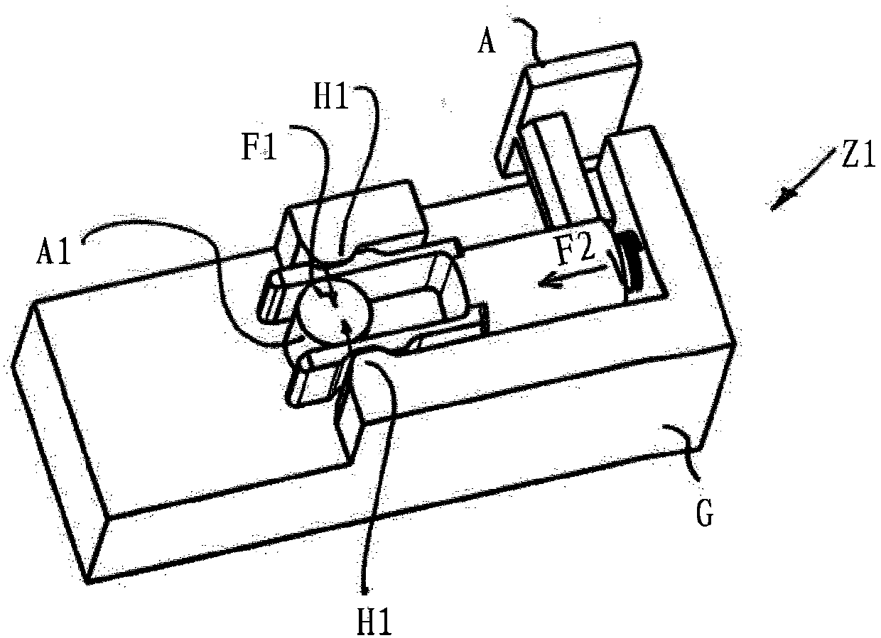
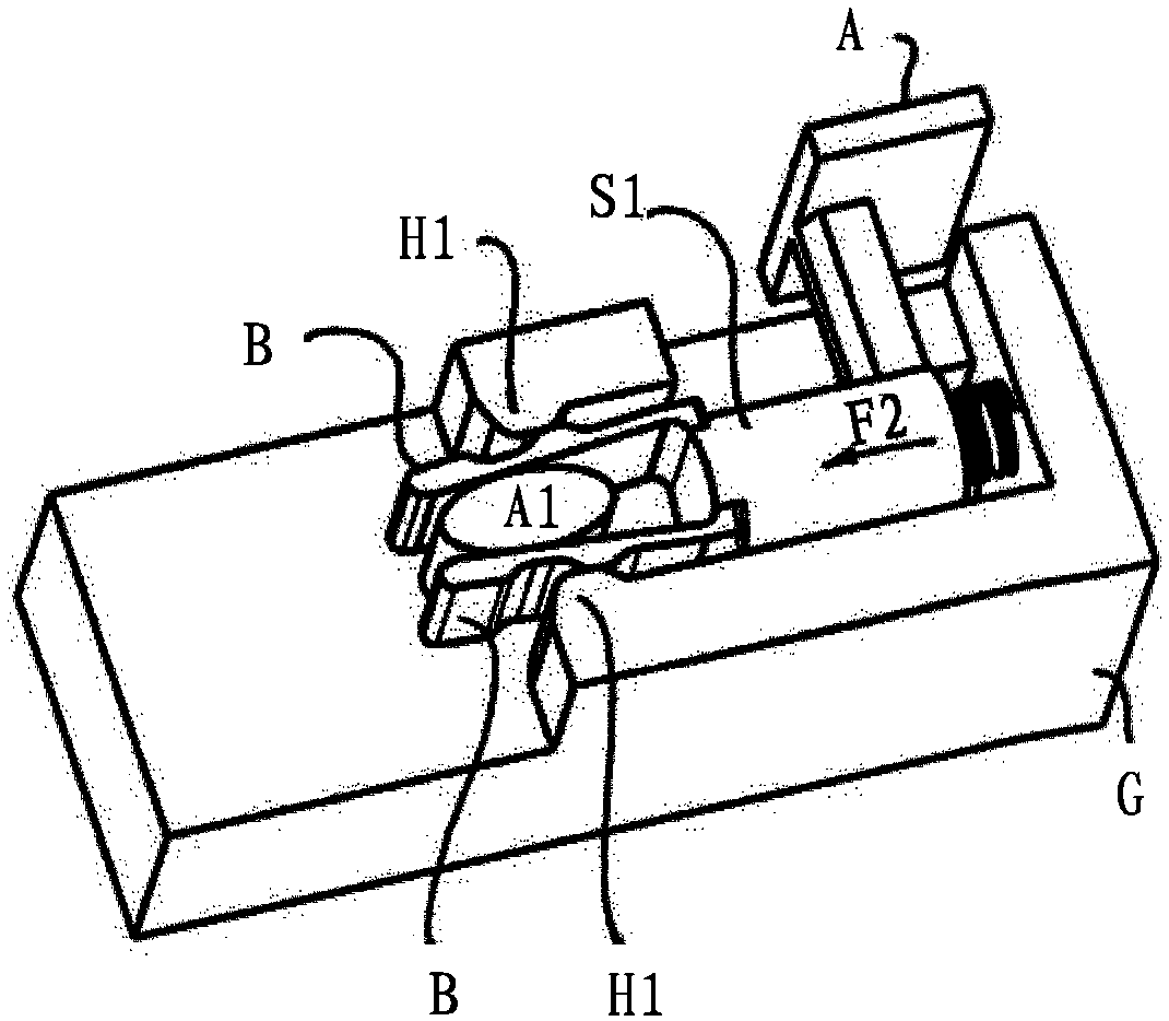
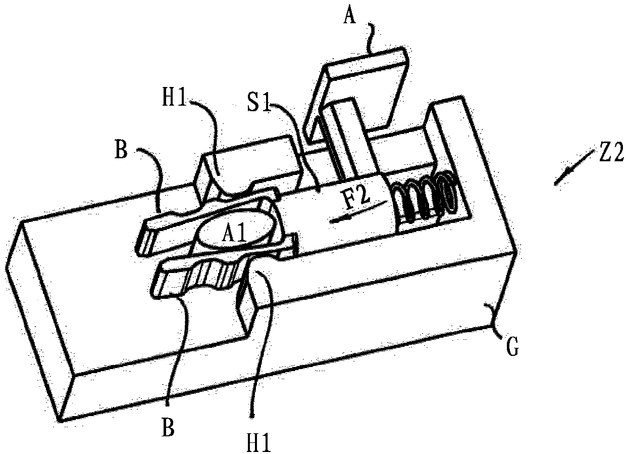
[0030] figure 1The device for thermally triggering or disconnecting the surge protector is shown in a first state Z1 , which device includes a display surface and a slider S1 . A force F2 is applied to the slide by means of a helical spring. For this purpose, the helical spring supports the housing G in which the slide S1 is mounted. Here, a helical spring is used as an energy store, wherein the force F2 is correspondingly high, causing the slide S1 to move. The slide S1 has a holding device, which is realized by two opposing jaws B.

[0031] Furthermore, a locking element A1 is provided on the housing G. The locking element A1 is preferably in thermal contact with a heat source, in particular the surge protector, and is inserted loosely and held only by the jaw B.

[0032] Jaw B of holding device H1 is of flexible design, in particular made of a flexible plastic material. Furthermore, the jaw plates B each have an outwardly directed groove. The grooves serve there to re...


PUM


Abstract

The invention relates to a device for thermally triggering, separating, and/or signaling the state of a surge protector, comprising a blocking element on which a first force acts and the aggregate state and/or the outer shape of which changes when a threshold temperature is exceeded. Furthermore, a slide is provided which is blocked by the blocking element in a first state and on which a second force acts in order to convert the slide into a second state if the aggregate state and/or the outer shape of the blocking element has changed. A latch retaining device, which is connected to the slideand by means of which the blocking element indirectly blocks the slide and the second force is broken down into a sub-force component, acts on the blocking element in a clamping manner. Furthermore, the latch retaining device has at least one elastic flexible jaw which is supported against the blocking element and the surroundings of the slide in the first state, wherein the first force corresponds to the sub-force component.

Description

technical field [0001] The invention relates to a device for thermally triggering, disconnecting and / or signaling the state of an overvoltage protector according to claim 1, the device comprising a locking element to which a first force is applied on the locking element and which changes its state of aggregation and / or its external structure when the limit temperature is exceeded. Background technique [0002] DE 10 2006 037 551 B4 shows a locking disconnection device, in which a movable welded profile is stressed by a pretensioned spring, but cannot be displaced as long as the welded pin blocks the movement path. If the welding pin melts due to a thermal overload, for example caused by a high current, the weld profile and thus the slide moves, so that for example an electrical circuit which outputs a warning signal is closed. [0003] DE 10 2010 061 110 A1 also discloses a thermal disconnection device, in which the first conductor section and the second conductor section a...

Claims


Application Information

Patent Timeline
Patent Type & Authority Applications(China)
IPC IPC(8): H01H37/46H01H73/22H01C7/12
CPCH01C7/126H01H37/323H01H37/46H01H71/18H01T1/14H01H73/22
Inventor U·施特朗费尔德S·希尔
Owner デーンエスエープルスツェオーカーゲー
Why Eureka
Try Eureka