A Current Decoupling Method Under Position Sensorless Control

A current decoupling and sensor technology, which is applied in the direction of controlling generators, controlling electromechanical brakes, controlling electromechanical transmissions, etc., can solve problems such as lack of research, and achieve the effects of improving estimation accuracy, sufficient decoupling, and improving performance

Active Publication Date: 2018-06-26
JINLING CUSTOMS TECH CENT
View PDF4 Cites 0 Cited by
  • Summary
  • Abstract
  • Description
  • Claims
  • Application Information

AI Technical Summary

Problems solved by technology

However, there is still a lack of research on how to consider the influence of rotor position estimation errors on current coupling in the current decoupling method, which is also the practical problem that this application is dedicated to solving

Method used


Image

  • A Current Decoupling Method Under Position Sensorless Control
  • A Current Decoupling Method Under Position Sensorless Control
  • A Current Decoupling Method Under Position Sensorless Control

Examples


Embodiment 1

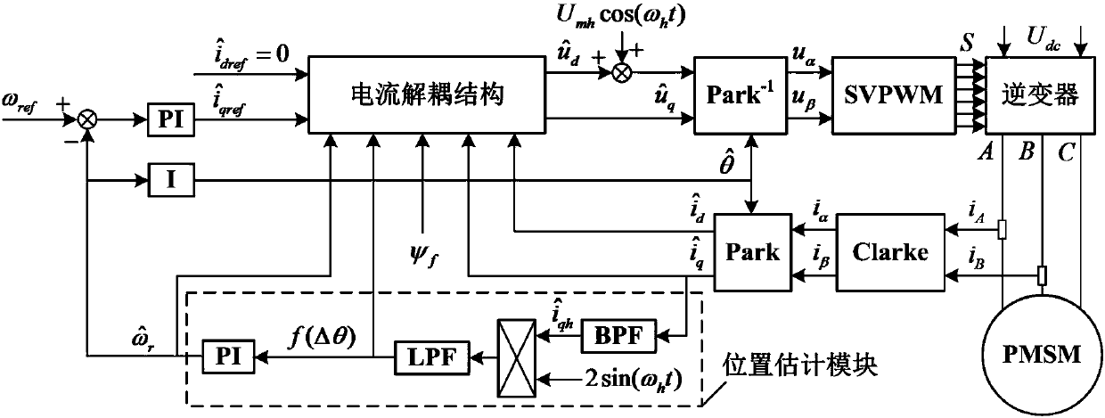
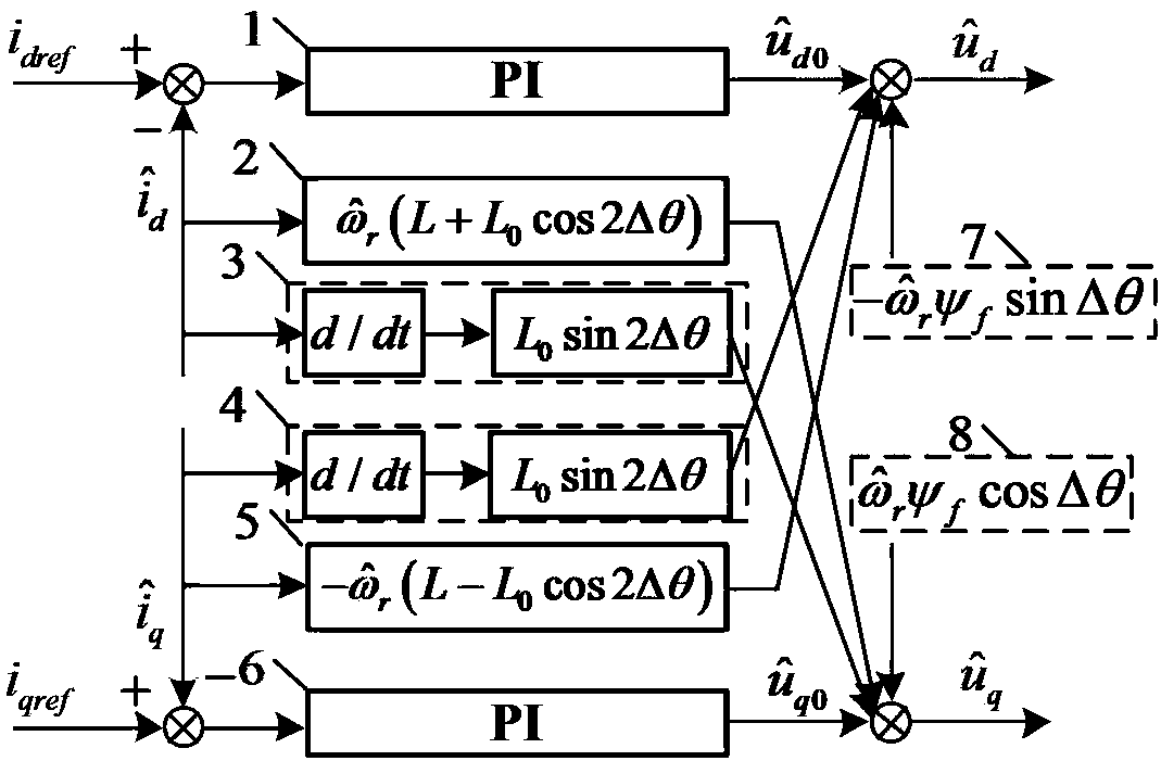
[0042] Such as Figure 5 Shown, the specific implementation steps of the present invention are:

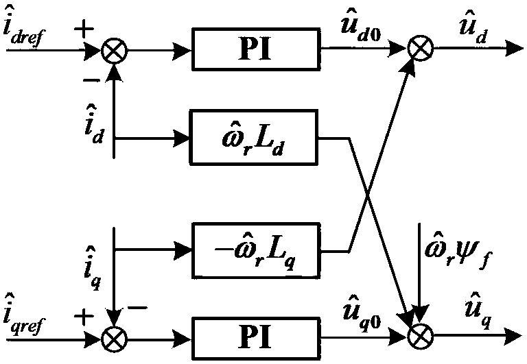
[0043] 1) The decoupling algorithm is used to obtain the estimated direct-axis and quadrature-axis voltage reference values.

[0044] 1.1) Obtain the estimated direct axis voltage reference value

[0045] 1.1.1) will estimate the direct axis current reference value with the estimated direct axis current feedback value The difference of the PI regulator is used as the input to read the output of the PI regulator in and The initial value of is 0.

[0046] 1.1.2) will estimate the quadrature axis current feedback value Estimated Rotor Angular Velocity and quadrature axis inductance L q Multiply the three to calculate the estimated quadrature axis current feedback value related items in and The initial value of 0; L q It is the parameter of the motor body, which can generally be obtained directly from the nameplate.

[0047] 1.1.3) will estimate the derivativ...


PUM


Abstract

The present invention provides a sensorless control type current decoupling method. The rotor position estimation error is taken into account for the current coupling effect, so that the direct-axis current and the quadrature-axis current are more fully decoupled. In this way, the rotor position estimation error is reduced, and the control performance of the system is improved. Based on the method, in the sensorless control mode of a permanent magnet synchronous motor, all parameters for controlling the current decoupling process are estimates, so that the rotor position estimation error greatly influences the current coupling effect, wherein the partial coupling term of the current is related to the rotor position estimation error, the direct-axis current saturation value and the quadrature-axis inductance difference.

Description

technical field [0001] The invention relates to the field of motor control, in particular to a current decoupling method under the control of no position sensor. Background technique [0002] Permanent magnet synchronous motors have been widely used in industry due to their small volume and weight, high power factor and good control performance. In its control process, it is necessary to obtain accurate rotor position information, which is often obtained by mechanical sensors, such as photoelectric encoders and resolvers. But this increases the volume, weight and cost of the system, and such sensors are prone to failure in some places with severe vibration and humidity. In order to solve the above problems, many scholars have carried out research on the sensorless control technology of permanent magnet synchronous motors. [0003] J.H.Jang, S.K.Sul, J.I.Ha, "Sensorless Drive of Surface-Mounted Permanent-Magnet Motor by High-Frequency Signal Injection Based on Magnetic Salie...

Claims


Application Information

Patent Timeline
Patent Type & Authority Patents(China)
IPC IPC(8): H02P21/22H02P21/18
Inventor 陈建松周融洪颖刘丽东柏文杰刘兵魏佳丹
Owner JINLING CUSTOMS TECH CENT
Why Eureka
Try Eureka