Equipment for twisting multifilament yarns

A kind of equipment and yarn technology, which is applied in the field of twisted multifilament yarn equipment, to achieve the effect of saving space, improving flexibility, and tight machine spacing

Active Publication Date: 2019-03-01
OERLIKON TEXTILE GMBH & CO KG
View PDF9 Cites 0 Cited by
  • Summary
  • Abstract
  • Description
  • Claims
  • Application Information

AI Technical Summary

Problems solved by technology

However, this can only be achieved with complex machine concepts

Method used


Image

  • Equipment for twisting multifilament yarns
  • Equipment for twisting multifilament yarns
  • Equipment for twisting multifilament yarns

Examples


Embodiment Construction

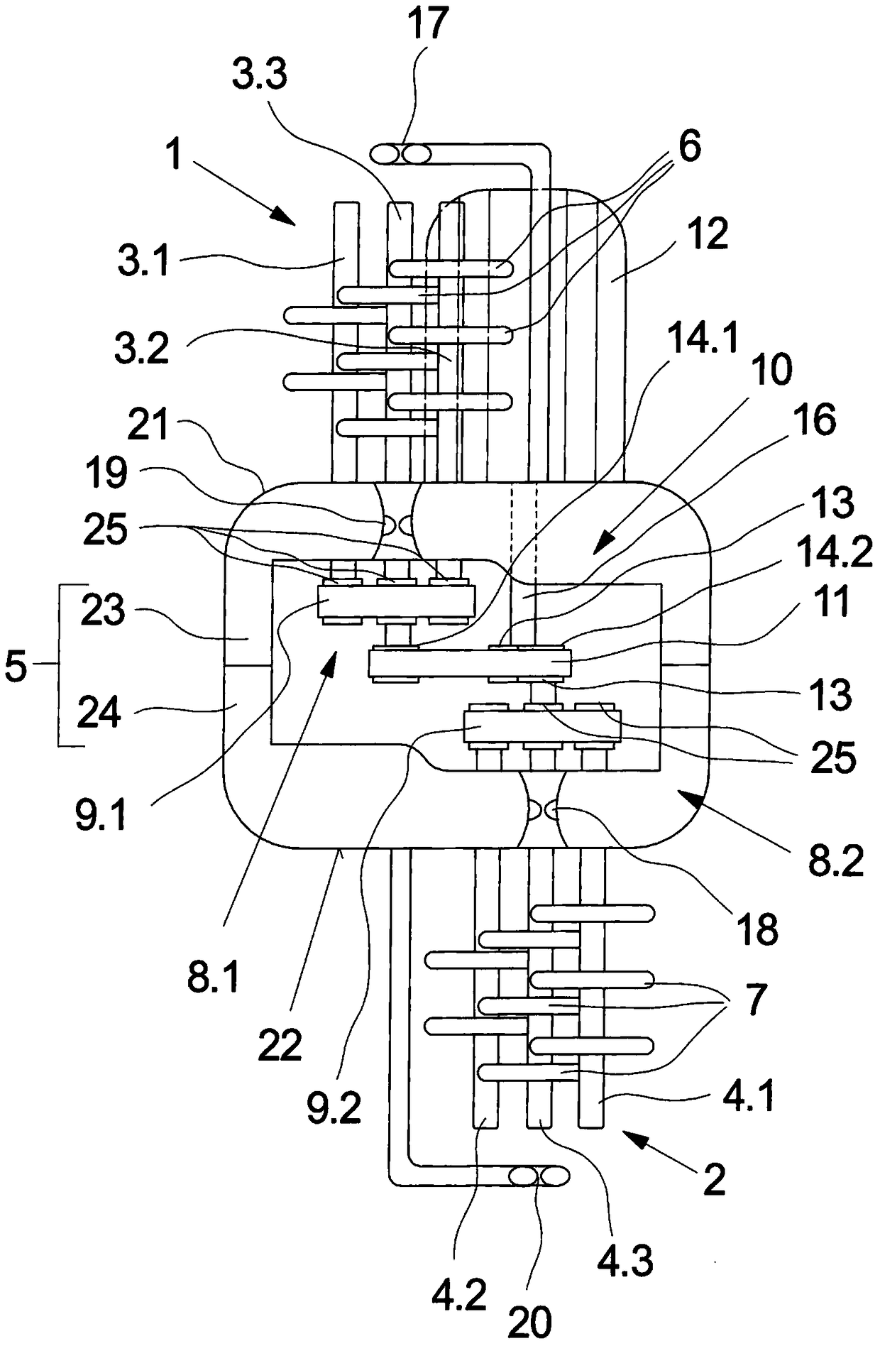
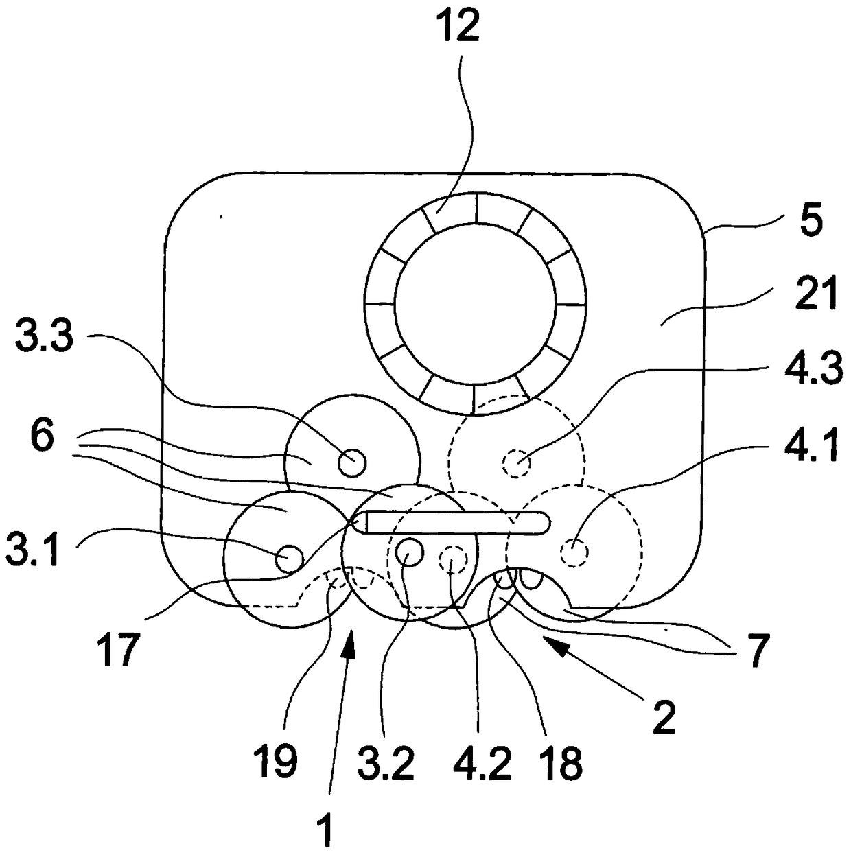
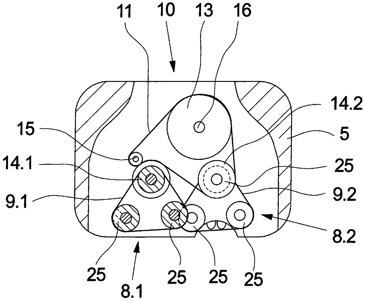
[0052] exist figure 1 , figure 2 and image 3 In , a first exemplary embodiment of the device for twisting multifilament yarns according to the invention is shown in various views. figure 1 The front view is shown schematically, figure 2 shows the floor plan schematically, and image 3 A cross section in the region of the drive is shown. The following description applies to all drawings as long as no specific reference is made to them.

[0053] The exemplary embodiment is configured as an assembly unit with an upper friction spindle arrangement 1 and a lower friction spindle arrangement 2 . The upper friction spindle arrangement 1 is arranged protrudingly on the upper side 21 of the spindle carrier 5 . The upper friction spindle arrangement 1 contains a total of three friction spindles 3.1, 3.2 and 3.3, which have a plurality of friction disks 6 spaced apart from one another and offset from one another on their peripheral surfaces. The friction discs 6 are arranged on...


PUM


Abstract

An apparatus for twisting multifilament threads, having a plurality of friction-spindle devices which have in each case one group of friction spindles having a plurality of friction discs which are retained in an overlapping manner is described. The friction spindles of the friction-spindle devices are rotatably retained in a protruding manner on a carrier. In order to implement particularly tight machine pitches for processing threads, according to the invention an upper one of the friction-spindle devices is retained on an upper side of the carrier and a lower one of the friction-spindle devices is retained on a lower side of the carrier.

Description

technical field [0001] The invention relates to an apparatus for twisting multifilament yarns. Background technique [0002] In the production of crimped synthetic threads, it is known to generate in multifilament threads a frictionally introduced false twist which is heat-set in the form of filaments of the thread in the texturing zone by heat treatment. Devices for twisting multifilament threads in which the threads are guided on the peripheral surfaces of rotating and superimposed friction discs have proven successful for producing such false twists. This type of equipment is often used in what is known as a texturing machine where several processing positions are arranged. A plant with a plurality of friction spindle arrangements arranged next to one another is particularly preferred for the production of composite wires. An apparatus of this type for twisting multifilament yarns is disclosed, for example, in US 4,584,831. [0003] For this purpose, in known devices, ...

Claims


Application Information

Patent Timeline
Patent Type & Authority Patents(China)
IPC IPC(8): D02G1/08D01H7/92
CPCD02G1/082
Inventor 王小兵胡欢庆姜华吕祥
Owner OERLIKON TEXTILE GMBH & CO KG
Why Eureka
Try Eureka