Lubricating structure of a plunger pump

A kind of lubrication structure and plunger pump technology, applied in the field of hydraulic pump, to achieve the effect of reducing oil injection frequency and lasting lubrication

Active Publication Date: 2020-09-18
邱永祥
View PDF1 Cites 0 Cited by
  • Summary
  • Abstract
  • Description
  • Claims
  • Application Information

AI Technical Summary

Problems solved by technology

[0006] The purpose of the present invention is to solve the above-mentioned problems in the existing technology, and propose a lubricating structure of a plunger pump. The technical problem solved by the present invention is how to ensure that the plunger can be lubricated for a long time by one oil injection, and at the same time make the lubricating oil not easy to lubricate. leaking

Method used


Image

  • Lubricating structure of a plunger pump
  • Lubricating structure of a plunger pump
  • Lubricating structure of a plunger pump

Examples


Embodiment Construction

[0025] The following are specific embodiments of the present invention and in conjunction with the accompanying drawings, the technical solutions of the present invention are further described, but the present invention is not limited to these embodiments.

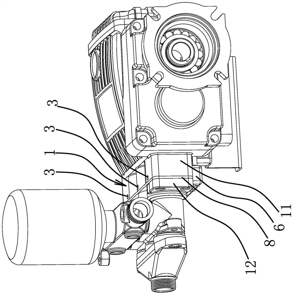
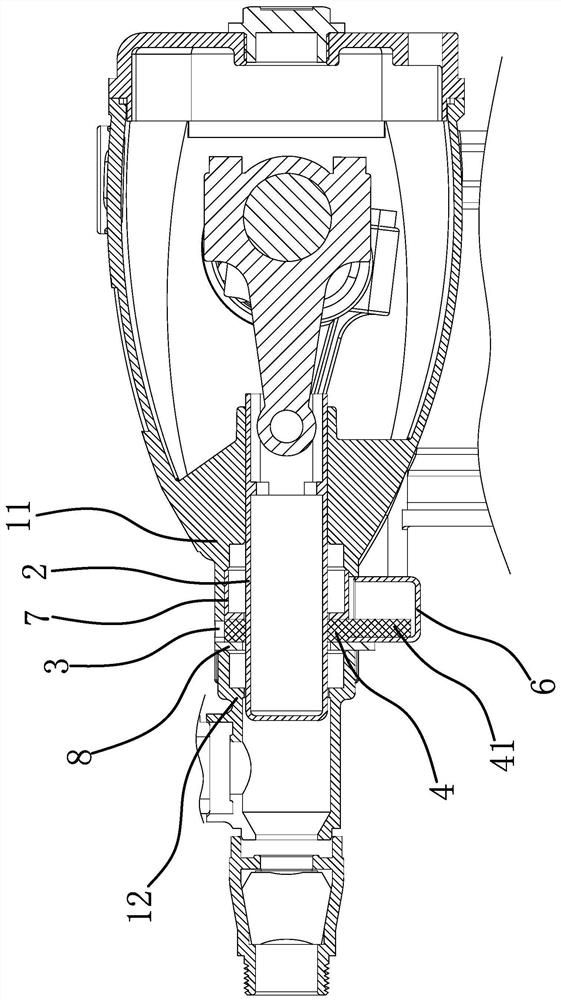
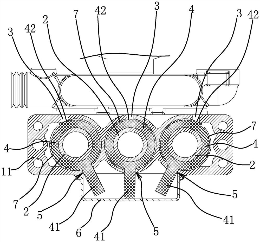
[0026] Specifically, as figure 1 and Figure 4 As shown, the plunger pump includes a pump body 1 and a plunger 2 located in the pump body 1 . The pump body 1 includes a crankcase 11 and a cylinder 12 fixedly connected to the crankcase 11 , one end of the plunger 2 is located in the cylinder 12 , and the other end of the plunger 2 is located in the crankcase 11 . Such as figure 2 and image 3 As shown, the lubricating structure includes an oil injection hole 3 arranged on the upper part of the crankcase body 11, a lubricating felt ring 4 positioned in the crankcase body 11 and sleeved on the plunger 2, and an oil leakage hole arranged at the lower part of the crankcase body 11. Holes 5 and lubricating felt rings 4 are ...


PUM


Abstract

The invention provides a lubricating structure of a plunger pump, belongs to the technical field of hydraulic pumps, and solves the problems that a plunger can be durably lubricated through one-time oil injection and lubricating oil is unlikely to leak. The plunger pump comprises a pump body and a plunger in the pump body; the lubricating structure comprises an oil injection hole, a lubricating felt collar and an oil leakage hole, wherein the oil injection hole is formed in the upper part of the pump body; the lubricating felt collar is located in the pump body and is arranged on the plunger in a sleeving manner; the oil injection hole is formed in the lower part of the pump body; the lubricating felt collar is made of an oil absorption material and is blocked between the oil injection hole and the oil leakage hole; an oil storage tank communicating with the oil leakage hole is arranged below the oil leakage hole; and an oil absorption part I is arranged on the lubricating felt collar, penetrates through the oil leakage hole, and stretches into the oil storage tank. Through the design, the lubricating structure greatly reduces the oil injection frequency, reduces the maintenance quantity of the plunger pump and can ensure the situation that lubricating oil is unlikely to leak when plenty of lubricating oil is injected at one time.

Description

technical field [0001] The invention belongs to the technical field of hydraulic pumps, and relates to a plunger pump, in particular to a lubricating structure of the plunger pump. Background technique [0002] The plunger pump is an important device in the hydraulic system. The plunger pump is widely used in high pressure, large flow and flow adjustment occasions, such as hydraulic presses, engineering machinery and ships, agricultural machinery and plant protection machinery and other fields. Among them, the working principle of the plunger pump is mainly to drive the connecting rod through the rotation of the crankshaft, and the plunger becomes a linear reciprocating motion to change the volume of the liquid cylinder periodically to achieve the purpose of sucking and discharging liquid. [0003] In order to ensure that the plunger can reciprocate at a long-term rated high speed, the plunger needs to be lubricated. The lubricating medium for the existing plunger lubricatio...

Claims


Application Information

Patent Timeline
Patent Type & Authority Patents(China)
IPC IPC(8): F04B53/18
CPCF04B53/18
Inventor 邱永祥
Owner 邱永祥
Why Eureka
Try Eureka