
A shared charging treasure rental cabinet

A charging treasure and rental cabinet technology, which is applied in the field of shared charging treasure rental equipment, to achieve the effects of improving utilization, ensuring safety, and improving rental efficiency

Active Publication Date: 2018-08-28
为梦充电(重庆)科技发展有限公司
View PDF7 Cites 0 Cited by
  • Summary
  • Abstract
  • Description
  • Claims
  • Application Information

AI Technical Summary

Problems solved by technology

[0004] The purpose of the present invention is to provide a shared charging treasure rental cabinet, which has the advantages of fast and convenient rental, real-time display of charging treasure status information, and accurate billing, which solves the existing problems of charging treasure rental cabinets in the existing market

Method used


Image

  • A shared charging treasure rental cabinet
  • A shared charging treasure rental cabinet
  • A shared charging treasure rental cabinet

Examples


Embodiment 1

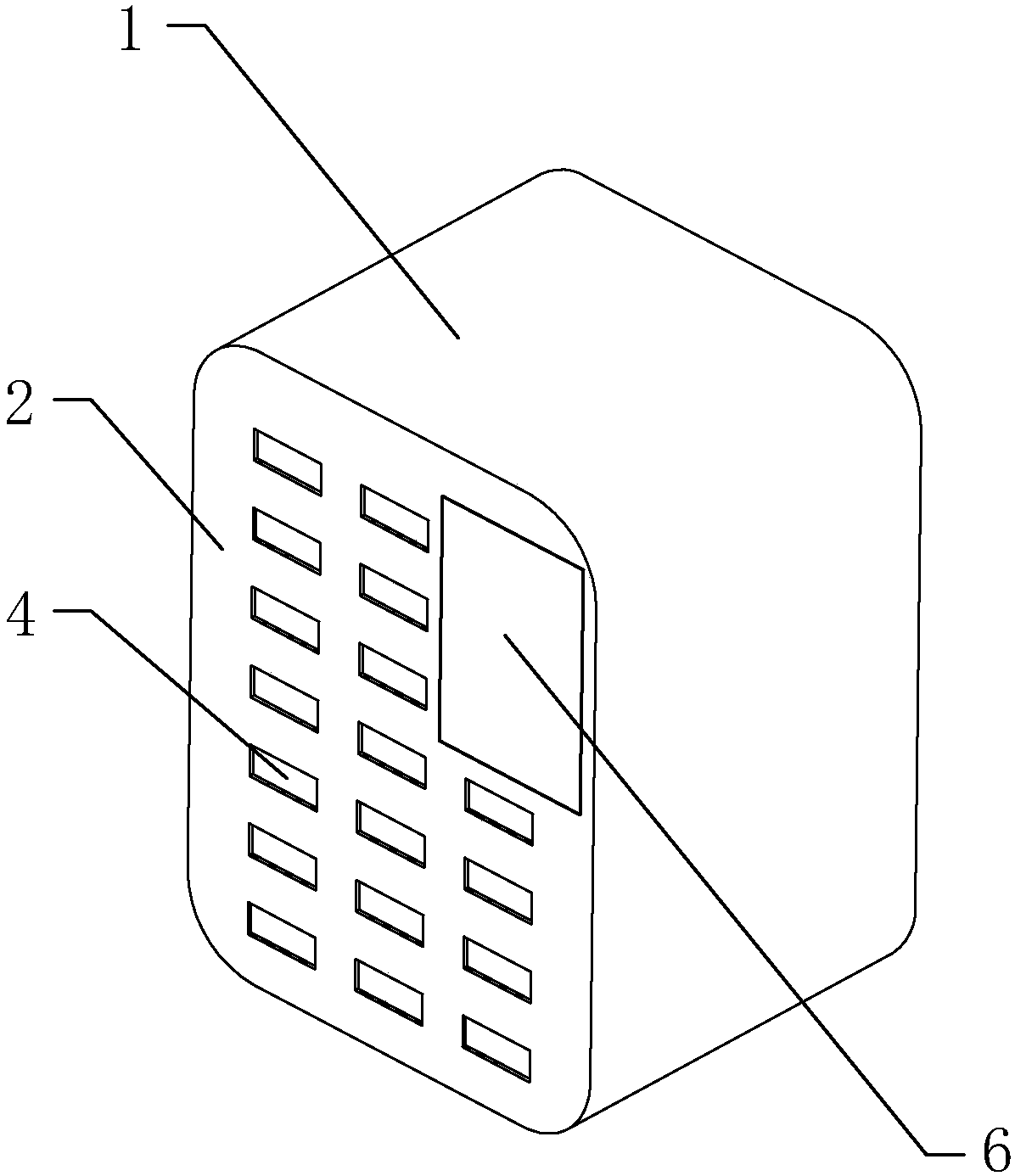
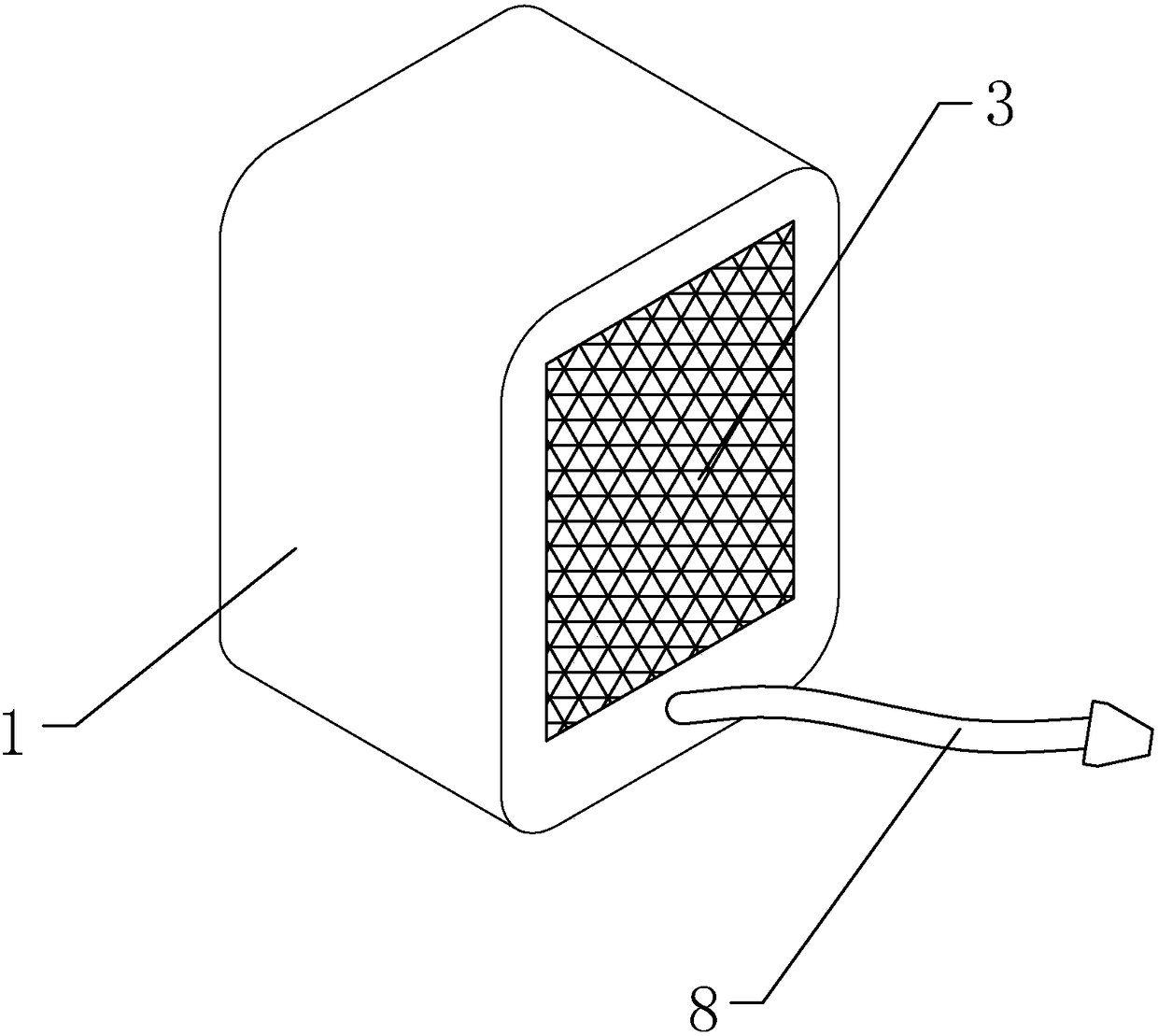
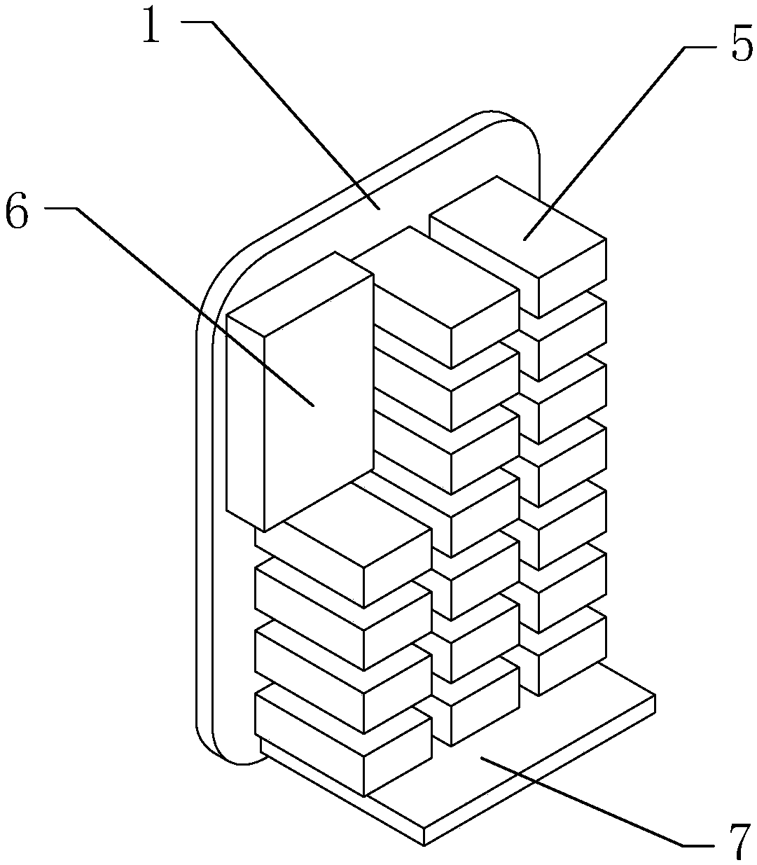
[0042] see Figure 1-7 , a shared charging treasure rental cabinet, including a cabinet body 1, the cabinet body 1 is provided with a front panel 2 and a rear panel 3, the front panel 2 is provided with a charging treasure inlet and outlet 4, and the front panel 2 and the The display 6 is fixedly connected, the front panel 2 is fixedly connected with the shell 501 provided on the charging treasure storage part 5, the charging treasure inlet and outlet 4 is aligned with the charging treasure storage part 5, and a circuit board is arranged inside the cabinet 1 7. The circuit board 7 is arranged under the power bank storage part 5, the circuit board 7 is electrically connected to the power cord 8, the power cord 8 extends out of the cabinet body 1, and the power bank storage part 5 is controlled by the shell 501, storage compartment 502, partition 503, charging throne 504, guide rail 505, placement slot 506, front baffle 507, rear baffle 508, light sensor 509, USB port 510, elect...

Embodiment 2

[0045] to combine Figure 8 to Figure 12 As shown, this embodiment makes the following improvements on the basis of Embodiment 1: a password input device 9 is installed on the front panel below the display. When the present invention is used for the first time, the password is set through the password input device. When the password is used for the second time, the power bank can be rented directly by inputting the password through the password input device. The problem of not being able to scan the code.

[0046] The password input device includes a first housing 91, a second housing 92 and a cover plate 93 connected in sequence; a finger insertion port 912 through the front and back is formed on the first housing, An installation cavity 914 is formed on the left side of the finger insertion opening, and a first installation opening 913 is formed on the front side of the first housing corresponding to the installation cavity, and a connecting wall 911 is formed on the outer ...


PUM


Abstract

The invention discloses a shared charging treasure rental cabinet. The cabinet body is provided with a front panel and a rear panel. The front panel is provided with a charging treasure inlet and outlet. It is fixedly connected with the shell provided on the storage part of the power bank, the inlet and outlet of the power bank are aligned with the storage part of the power bank, a circuit board is arranged in the cabinet, and the circuit board is arranged under the storage part of the power bank. The circuit board is electrically connected with the power line, and the power line extends out of the cabinet. The invention controls the charging process and billing function of the charging treasure through the circuit board and the smart chip, and can read and display the status information of the charging treasure in the charging treasure rental cabinet in real time, and the user can selectively rent the charging treasure according to the demand, so that the charging treasure Maximize the utilization rate, improve leasing efficiency, and increase the convenience of leasing, which is worth promoting.

Description

technical field [0001] The invention relates to the technical field of shared power bank rental equipment, in particular to a shared power bank rental cabinet. Background technique [0002] The public sharing economy generally refers to a new economic model based on strangers and the temporary transfer of the right to use items for the main purpose of obtaining certain rewards. Its essence is to integrate offline idle items, labor, education and medical resources. Some also say that the sharing economy is that people enjoy social resources fairly, pay and benefit in different ways, and jointly obtain economic dividends. This kind of sharing is more realized through the Internet as a medium. [0003] Shared power bank refers to the charging rental equipment provided by the enterprise. Users only need to rent the power bank through a designated method. After the power bank is successfully returned, the corresponding rental fee will be deducted. There are many shared product...

Claims


Application Information

Patent Timeline
Patent Type & Authority Patents(China)
IPC IPC(8): G07F17/00G06K9/00
CPCG07F17/0042G06V40/13G06V40/1365
Inventor 江佳辉
Owner 为梦充电(重庆)科技发展有限公司
Learn More