Power plug assembly

A component and power technology, applied in the field of electric power, can solve problems such as burning of electrical equipment, power outage of electrical equipment, long plugs and wires of electrical equipment, etc., to achieve safe and stable power supply connection, increase the stability of power supply, reduce Effects of electric shock accidents

Active Publication Date: 2017-09-22
仪征市长恒电器有限公司
View PDF6 Cites 7 Cited by
  • Summary
  • Abstract
  • Description
  • Claims
  • Application Information

AI Technical Summary

Problems solved by technology

[0002] Nowadays, the power-on use of electrical equipment is to directly insert the plug connected to the electrical equipment into the power supply slot of the socket to plug in the power supply, but the power connection between the socket and the power supply will always be in the power-on state. It is convenient, but the wire between the plug and the electrical equipment is long, and there is no other component to lock the plug after the plug is inserted into the power supply tank. In the event of an accidental collision, it is easy to cause the plug to be detached from the power supply tank, resulting in a sudden power failure of the electrical equipment, and even a reduction in the service life of the electrical equipment. In severe cases, it will directly cause the electrical equipment to burn. There is a risk of unstable power supply connection between the plug and the power supply slot. In addition, when the electrical equipment is not in use, the plug is often pulled out from the power supply slot, which will cause the power supply slot to be exposed on the ground. Outside, if there is a child in the family who inserts a finger or a metal rod directly into the power supply groove of the socket, it will cause an electric shock accident for the child, and even cause life danger to the child. Therefore, there is a greater potential safety hazard

Method used


Image

  • Power plug assembly
  • Power plug assembly
  • Power plug assembly

Examples


Embodiment Construction

[0023] The preferred embodiments of the present invention will be described in detail below in conjunction with the accompanying drawings, so that the advantages and features of the present invention can be more easily understood by those skilled in the art, so as to define the protection scope of the present invention more clearly.

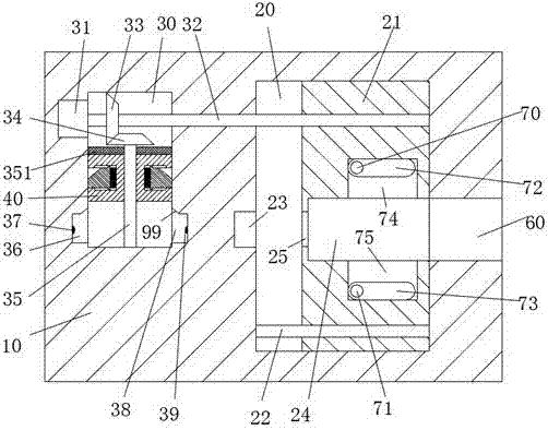
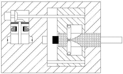
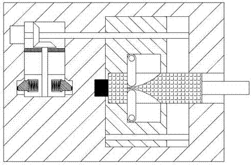
[0024] refer to Figure 1-7A power plug assembly shown includes a socket housing 10 and a plug device, the socket housing 10 is provided with a left movement slot 30 , and the socket housing 10 is located on the right side of the left movement slot 30 The right side is also provided with a right movement groove 20, the right end surface of the socket housing 10 is provided with an insertion groove 60 communicating with the right movement groove 20, and the left end wall of the right movement groove 20 is provided with a 60 relative to the power supply slot 23, the first moving block 21 that can slide left and right is arranged in the right moving...


PUM


Abstract

The invention discloses a power plug assembly. The power plug assembly comprises a socket shell and a plug device. The socket shell is internally provided with a left motion groove, and a right motion groove is arranged at the right side of the left motion groove in the socket shell. The right end surface of the socket shell is provided with an insert groove communicated with the right motion groove. The left wall of the right motion groove is provided with a power supply groove opposite to the insert groove. The right motion groove is provided with a first motion block capable of sliding left and right. The whole structure of the power plug assembly is simple, and power supply connection is safe and stable, so that electric shock accidents in life are prevented, and people are protected; and a power connection operation between the plug and the power supply groove is completed automatically through work of a first motor, power connection between the socket shell and the plug device is easy, and electric shock accidents are prevented in power connection, so that the power plug assembly meets existing use requirements and is applicable to promotion.

Description

technical field [0001] The invention relates to the field of electric power, in particular to an electric power plug assembly. Background technique [0002] Nowadays, the power-on use of electrical equipment is to directly insert the plug connected to the electrical equipment into the power supply slot of the socket to plug in the power supply, but the power connection between the socket and the power supply will always be in the power-on state. It is convenient, but the wire between the plug and the electrical equipment is long, and there is no other component to lock the plug after the plug is inserted into the power supply tank. In the event of an accidental collision, it is easy to cause the plug to be detached from the power supply tank, resulting in a sudden power failure of the electrical equipment, and even a reduction in the service life of the electrical equipment. In severe cases, it will directly cause the electrical equipment to burn. There is a risk of unstabl...

Claims


Application Information

Patent Timeline
IPC IPC(8): H01R13/639H01R13/629H01R13/70
CPCH01R13/629H01R13/639H01R13/701
Inventor 张金发
Owner 仪征市长恒电器有限公司
Why Eureka
Try Eureka