Heart valve prosthesis with clamping devices

A clamping device and heart valve technology, which is applied in the field of medical devices and can solve problems such as unstable prosthesis fixation and paravalvular leakage

Active Publication Date: 2017-09-29
NINGBO JENSCARE BIOTECHNOLOGY CO LTD
View PDF13 Cites 11 Cited by
  • Summary
  • Abstract
  • Description
  • Claims
  • Application Information

AI Technical Summary

Problems solved by technology

The technology of the present invention has the characteristics of accurate positioning, stable clamping, firm clamping, reduced left ventricular outflow tract area obstruction, and reduced paravalvular leakage, and solves the problems of weak fixation

Method used


Image

  • Heart valve prosthesis with clamping devices
  • Heart valve prosthesis with clamping devices
  • Heart valve prosthesis with clamping devices

Examples


specific Embodiment 1

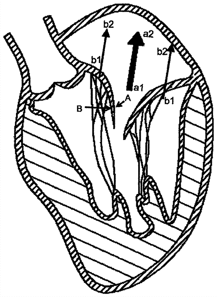
[0058] When the heart valve prosthesis is used to treat mitral valve disease, Figure 1a A schematic cross-sectional view of the left ventricle is shown, wherein, a1-a2 is the central axis of the blood flow direction of the valve sewing section, also known as the axis line of the valve sewing section, and b1-b2 is the clamping The central axis of the blood flow direction of the device, a1-a2 is parallel to b1-b2, plane A is the closing surface of the native mitral valve leaflet, and plane B is the opposite side of the closing surface of the native mitral valve leaflet, The radial direction of the cross-section of the valve sewing section is called the radial direction of the valve sewing section, the circumferential surface of the valve sewing section close to the axis line is the inner surface, and the valve sewing section The circumferential surface of the section away from the axis is the outer surface.

[0059] In one embodiment of the present invention, as Figure 1b As...

specific Embodiment 2

[0062] In order to illustrate the working principle of the present invention better, the release process of the artificial valve prosthesis of the present invention will be described step by step below:

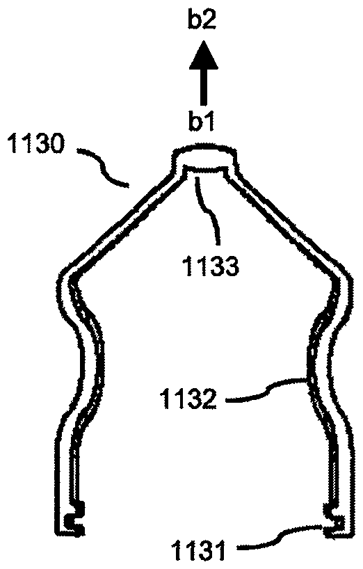
[0063] Such as Figure 2a As shown, the heart valve prosthesis is accessed through the delivery system 2300 from the apex when the heart valve prosthesis is used to treat mitral valve disease. Such as Figure 2b As shown, the delivery system 2300 includes a handle 2310, an outer sheath 2320 and an inner sheath 2330. By operating the handle 2310, the clamping device 1130 placed in the outer sheath 2320 is released. In an embodiment, the number of the clamping device 1130 is one, and at this time, the stent and the artificial valve are still partially or completely compressed in the inner sheath 2330 . Such as Figure 2c-2d As shown, the free end 1133 of the clamping device 1130 opens away from the inside of the bracket to the outside of the bracket, forming an angle α. Due ...

specific Embodiment 3

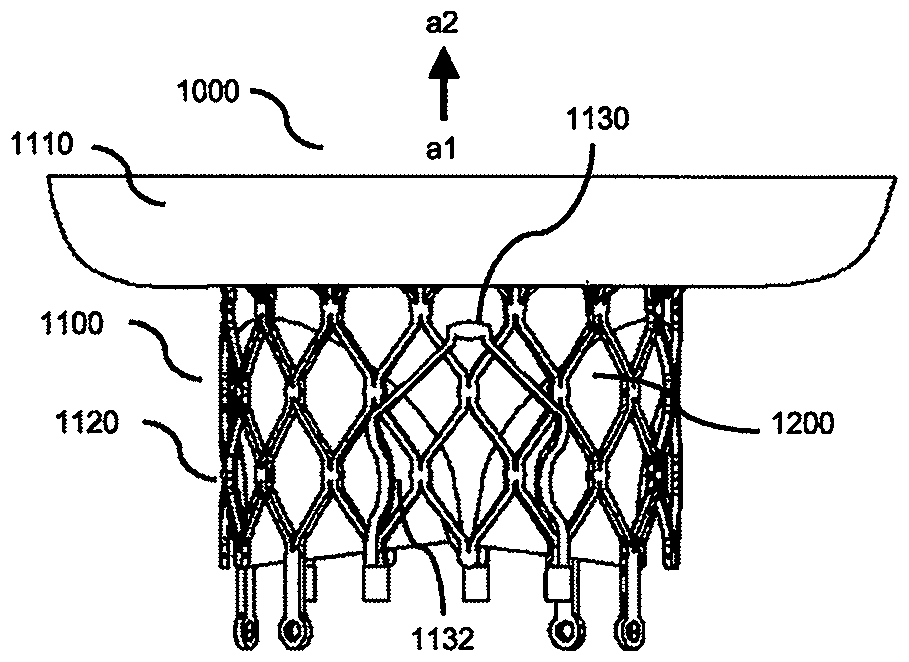
[0066] In one embodiment of the present invention, as Figures 5a-5b As shown, a heart valve prosthesis 1000 with a clamping device includes a stent 1100 and an artificial valve 1200. The stent 1100 is made of shape memory alloy and includes an atrium segment 1110, a valve sewing segment 1120 and two clamping device 1130, the artificial valve 1200 is fixedly connected to the valve sewing section 1120, and the axis a1-a2 of the valve sewing section 1120 is as follows Figure 5a As shown, the atrium segment 1110 is integrally cut with the valve sewing segment 1120, the proximal end of the atrium segment 1110 is connected to the distal end of the valve sewing segment 1120, and the atrium segment 1110 is sewn Manufactured with a polymer or animal-derived material (not shown) that can reduce or prevent blood flow through, the atrial segment 1110 is flared to the outside of the valve sewn segment, and the atrial segment 1110 is sewn on the valve The projected area in the radial dir...


PUM


Abstract

The invention relates to a heart valve prosthesis with clamping devices. The heart valve prosthesis comprises a stent and an artificial valve. The stent comprises a heat atrium section, a valve sewing section and at least one clamping device, the artificial valve is fixedly connected onto the valve sewing section, a proximal end of the heart atrium section is fixedly connected with a distal end of the valve sewing section, a reinforcement structure is arranged on the heart atrium section, one end of the reinforcement structure is fixedly connected onto the heart atrium section or is fixedly connected onto materials which are fixedly connected with the heart atrium section and are used for reducing blood or stopping the blood from flowing through the materials, the other end of the reinforcement structure is opened towards the outside of the valve sewing section in natural states, the reinforcement structure and the materials are abutted to autologous valve ring tissues and/or heart atrium tissues after the artificial heart valve prosthesis is completely released, a part of each clamping device is abutted to the outer surface of the valve sewing section in the natural states, at least one bent section which is inwardly bent towards the valve sewing section is arranged on each clamping portion, and a part of each bent portion extends into grid gaps of the valve sewing section.

Description

Technical field: [0001] The invention belongs to the field of medical equipment, in particular to a heart valve prosthesis with a clamping device. Background technique: [0002] The mitral valve is located in the left ventricle. The mitral valve includes an anterior leaflet (anterior leaflet), a posterior leaflet (posterior leaflet) and a junctional area (anterior junctional area and posterior junctional area). There is no chordal attachment to the septum. Due to its complex physiology, it is also referred to as the mitral valve device. The mitral annulus is a band of fibrous tissue attached to the edge of the left atrioventricular orifice. It is an irregular "D" shape. The anterior third of the mitral annulus is the continuous part of the anterior valve and the aorta. The anterior and posterior valves The angle formed by the corresponding atrium and the mitral valve ring is also different, and the left atrial appendage is attached to the atrium. Mitral valve insufficienc...

Claims


Application Information

Patent Timeline
IPC IPC(8): A61F2/24
Inventor 陈志李佳楠曹鹏李毅斌徐志云宋智钢
Owner NINGBO JENSCARE BIOTECHNOLOGY CO LTD
Why Eureka
Try Eureka