Environmental-friendly dust removal device

A facility and environmentally friendly technology, applied in electrical components, coupling devices, circuits, etc., can solve problems such as electric shock accidents of plugs, power failure of dust collectors, and plug kicks, etc., to achieve simple structure, safe and stable power supply, and increased stability. Effect

Inactive Publication Date: 2017-09-29
乐绪春
View PDF5 Cites 11 Cited by
  • Summary
  • Abstract
  • Description
  • Claims
  • Application Information

AI Technical Summary

Problems solved by technology

[0002] When cleaning dust, dust is often sucked by a dust collector, which can effectively and quickly clean the dust. When using the dust collector, it must be dragged around to clean the dust in every corner. The plug and socket of the existing dust collector They are generally connected by friction fit, and there is no other locking device. Therefore, when dragging the dust collector to clean up dust in different positions, it is easy to pull the plug of the dust collector apart, or it is easy to kick the plug when accidentally tripping over it. Therefore, the power failure of the dust collector will affect the use, and the existing sockets connected to the dust collector are directly charged, so electric shock accidents are likely to occur when plugging the plug

Method used


Image

  • Environmental-friendly dust removal device
  • Environmental-friendly dust removal device
  • Environmental-friendly dust removal device

Examples


Embodiment Construction

[0020] The preferred embodiments of the present invention will be described in detail below in conjunction with the accompanying drawings, so that the advantages and features of the present invention can be more easily understood by those skilled in the art, so as to define the protection scope of the present invention more clearly.

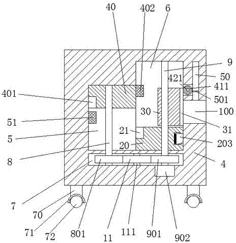
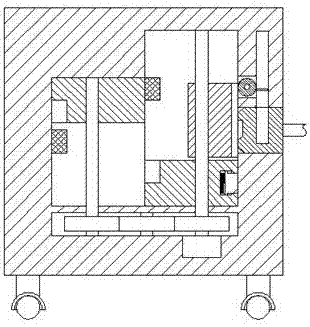
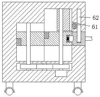
[0021] refer to Figure 1-6 The shown environment-friendly dust removal facility includes a frame body 4 and an electrical connector 10 for connecting with the frame body 4 for electrical connection, and the frame body 4 includes a left sliding Cavity 5 and the right sliding cavity 6 that communicates with described left sliding cavity 5, described left sliding cavity 5 and the described rack body 4 below right sliding cavity 6 are provided with tooth plate cavity 7, and described right The middle part of the right end of the sliding chamber 6 is provided with a latch groove 100 communicating with the outside of the frame body 4 , and an upwardly...


PUM


Abstract

The invention discloses an environmental-friendly dust removal device. The environmental-friendly dust removal device comprises a rack and an electrical connector, wherein the electrical connector is electrically connected with the rack in a matching way, the rack comprises a left sliding cavity and a right sliding cavity, the left sliding cavity is arranged in the rack, the right sliding cavity communicates with the left sliding cavity, a tooth disc cavity is formed in the rack below the left sliding cavity and the right sliding cavity, a plug pin groove is formed in a middle part of a right end part of the right sliding cavity and communicates with the exterior of the rack, a locking groove is arranged in an upper end part of the plug pin groove and extends upwards, a connection groove is connected between the locking groove above the plug pin groove and the right sliding cavity, and a left sliding block is arranged in the left sliding cavity and can slide upwards and downwards. The environmental-friendly dust removal device is simple in structure, relatively low in production cost and safe and stable in power supply, an electric shock accident in existing life is effectively prevented, the life safety of people is guaranteed, moreover, the power connection operation is relatively convenient, and the application demand of existing power connection is satisfied.

Description

technical field [0001] The invention relates to the field of dust removal equipment, in particular to an environment-friendly dust removal facility. Background technique [0002] When cleaning dust, dust is often sucked by a dust collector, which can effectively and quickly clean the dust. When using the dust collector, it must be dragged around to clean the dust in every corner. The plug and socket of the existing dust collector Generally, they are connected by friction fit, and there is no other locking device. Therefore, when dragging the dust collector to clean up dust in different positions, it is easy to pull the plug of the dust collector apart, or it is easy to kick the plug when accidentally tripping over it. Open, so that the power failure of the dust collector affects the use, and the existing sockets connected to the dust collector are directly charged, so electric shock accidents are likely to occur when plugging the plug. Contents of the invention [0003] T...

Claims


Application Information

Patent Timeline
Patent Type & Authority Applications(China)
IPC IPC(8): H01R13/629H01R13/631H01R13/642
CPCH01R13/629H01R13/631H01R13/642
Inventor 乐绪春
Owner 乐绪春
Why Eureka
Try Eureka