
A cable well structure

A cable well and cable well cover technology, which is applied in underwater structures, infrastructure engineering, construction, etc., can solve problems affecting the safe operation of cables, loss of cable well covers, water accumulation in cable wells, etc., achieve good anti-theft function and avoid being caught The effect of stealing

Active Publication Date: 2019-05-07
LISHUI POWER SUPPLY COMPANY OF STATE GRID ZHEJIANG ELECTRIC POWER +2
View PDF5 Cites 0 Cited by
  • Summary
  • Abstract
  • Description
  • Claims
  • Application Information

AI Technical Summary

Problems solved by technology

The current cable well often has water accumulation in the cable well, and the water in the cable well cannot be discharged in time
After the cable well is flooded, it will affect the safe operation of the cable and cause potential safety hazards
[0003] On the other hand, the theft of cable well covers is also constantly occurring. The theft of cable well covers will not only cause the loss of the cable well covers themselves, but also cause the cables in the cable wells to be exposed and easily damaged, and if the cable wells without well covers are not found in time , will bring safety hazards to pedestrians and vehicles

Method used


Image

  • A cable well structure
  • A cable well structure
  • A cable well structure

Examples


Embodiment 1

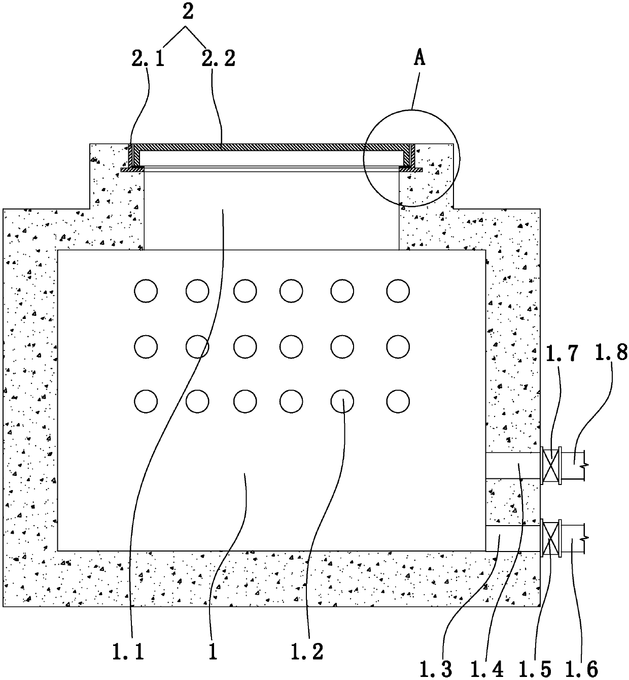
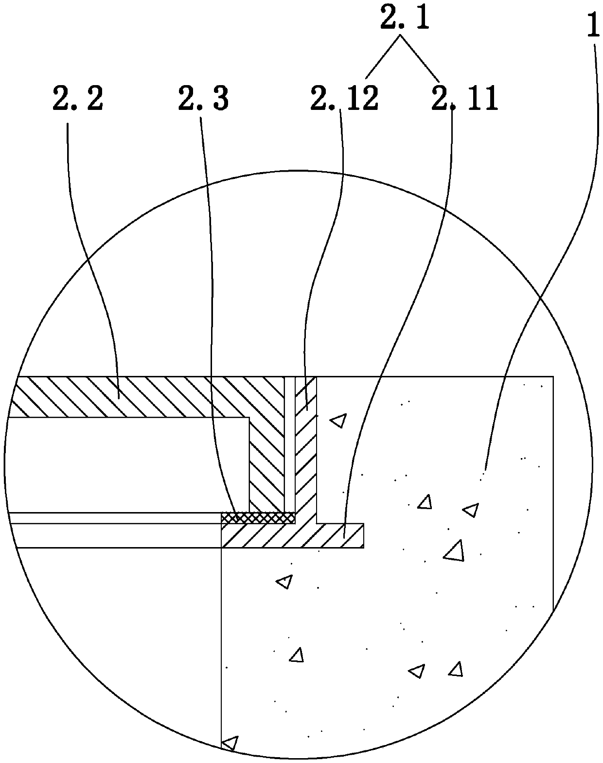
[0032] Embodiment 1: as figure 1 , figure 2 As shown, a cable shaft structure includes a shaft 1 arranged on the road surface and a cable shaft cover device 2 arranged on the wellhead 1.1 of the shaft for sealing the wellhead. The cable well cover device includes a seat ring 2.1 and a well cover 2.2. The seat ring is buried in the wellhead of the shaft. The seat ring includes an annular seat plate 2.11 and a vertical limit sleeve 2.12 arranged on the upper surface of the annular seat plate. The vertical limit sleeve is a circular sleeve. An annular sealing gasket 2.3 is arranged on the upper surface of the annular seat plate and is located in the vertical limiting sleeve. The manhole cover is round. The well cover is arranged in the vertical stop sleeve, and the lower surface of the well cover is close to the annular sealing gasket.

[0033] The side wall of the shaft is provided with a plurality of cable passage holes 1.2 which run through the inner and outer sides of ...

Embodiment 2

[0035] Embodiment 2, the remaining structure of this embodiment is with reference to embodiment 1, and its difference is:

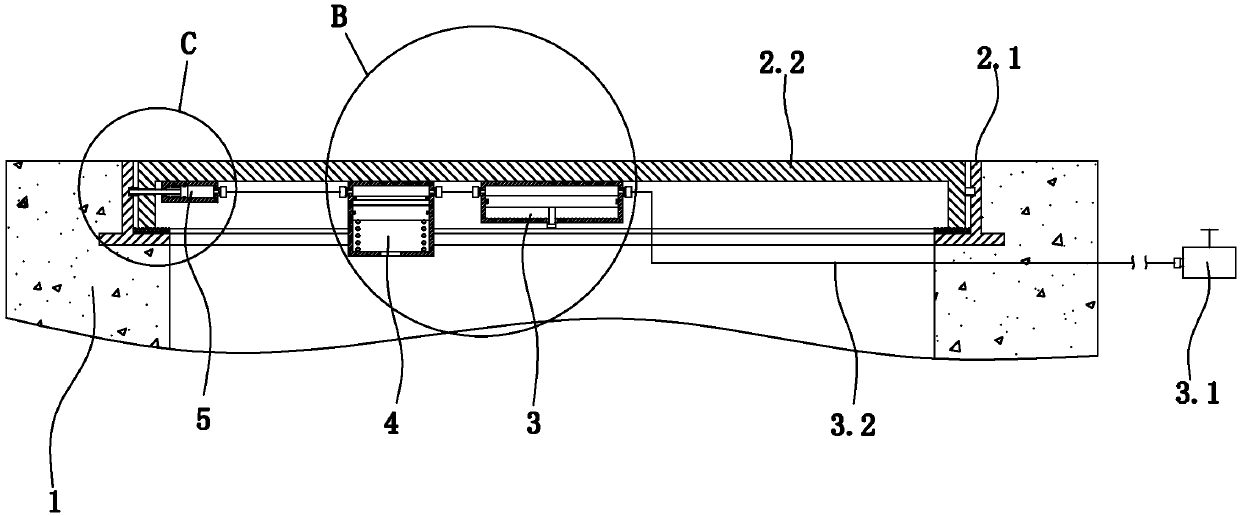
[0036] Such as image 3 As shown, a cable shaft structure also includes a trigger actuator 3 , a flexible buffer device 4 and three anti-theft locking devices 5 . The lower surface of the well cover is provided with a well cover groove 2.21, and the cross section of the well cover groove is circular.

[0037] Such as image 3 , Figure 4 As shown, the triggering actuator includes a switch valve 3.1, a vertical actuator cylinder 3.3 arranged on the bottom surface of the well cover groove, an actuator piston 3.4 slidingly arranged in the vertical actuator cylinder, and an actuator piston 3.4 arranged on the outer side of the vertical actuator cylinder. The first actuator cylinder interface 3.7 and the second actuator cylinder interface 3.8 on the top, the trigger rod through hole arranged on the lower end surface of the vertical actuator cylinder and the...


PUM


Abstract

The invention discloses a cable well structure and aims at providing a cable well structure capable of effectively solving the problem that water is accumulated in a cable well, accumulated water in the cable well cannot be discharged in time, and consequently safe running of a cable is influenced. The cable well structure comprises a vertical well arranged on the surface of a road and a cable well lid device arranged on a well mouth of the vertical well. The cable well lid device comprises a seat ring and a well lid. The seat ring is embedded in the well mouth of the vertical well. The seat ring comprises an annular seat plate and a vertical limiting sleeve arranged on the upper surface of the annular seat plate. An annular sealing gasket is arranged on the upper surface of the annular seat plate and located in the vertical limiting sleeve. The well lid is arranged in the vertical limiting sleeve. A main water outlet hole and an auxiliary water outlet hole penetrating the inner side face and the outer side face of the vertical well are formed in the lower portion of the side wall of the vertical well. The main water outlet hole communicates with a water discharging pipeline of the road through a main water discharging pipeline. The height of the position where the main water outlet hole is located is larger than the height of the position where the water discharging pipeline is located, and the auxiliary water outlet hole communicates with the water discharging pipeline of the road through an auxiliary water discharging pipeline.

Description

technical field [0001] The invention relates to an electric cable shaft, in particular to a cable shaft structure. Background technique [0002] With the continuous development of power grid construction, the demand for power cables is increasing, and cable shafts are widely used in cable laying. Current cable wells often have water accumulation in the cable wells, and the water accumulation in the cable wells cannot be discharged in time. After the cable well is flooded, it will affect the safe operation of the cable and cause potential safety hazards. [0003] On the other hand, the theft of cable well covers is also constantly occurring. The theft of cable well covers will not only cause the loss of the cable well covers themselves, but also cause the cables in the cable wells to be exposed and easily damaged, and if the cable wells without well covers are not found in time , will bring safety hazards to pedestrians and vehicles. Contents of the invention [0004] Th...

Claims


Application Information

Patent Timeline
Patent Type & Authority Patents(China)
IPC IPC(8): E02D29/12E02D29/14
CPCE02D29/12E02D29/1427E02D29/149
Inventor 陈新安凌军郦晨钟王华秋闫小芳张凯高逢宇李志文汪哓哓黄崇达周来潜丽光陈艳来
Owner LISHUI POWER SUPPLY COMPANY OF STATE GRID ZHEJIANG ELECTRIC POWER
Learn More