Rotatable bridge frame

A rotating and bridge technology, which is applied to the accessories of scaffolding, the scaffolding supported by the building structure, the support of the building structure, etc., can solve the problems of inconvenient construction and no safety precautions, and achieve improved construction efficiency, high practicability and safety. The effect of stability and connection

Pending Publication Date: 2017-10-10
福建建中建设科技有限责任公司
View PDF0 Cites 1 Cited by
  • Summary
  • Abstract
  • Description
  • Claims
  • Application Information

AI Technical Summary

Problems solved by technology

[0002] With the rapid economic growth and the rapid growth of urban population, the contradiction of decreasing urban construction land becomes more and more prominent. Super high-rise buildings have developed rapidly due to the advantages of less land, low cost of urban infrastructure, and can improve the appearance of the city. With more and more super high-rise buildings in modern engineering projects, the difficulty and quality requirements of construction technology are constantly increasing, especially when it comes to the construction of some irregular building appearances, the complexity and difficulty of construction technology management are getting higher and higher, especially Due to the limitation of geographical location and building construction site for exterior decoration, safety protection has become a major problem for super high-rise buildings. At present, domestic super high-rise building projects generally use hanging blue exterior decoration construction. There is no safety precaution specification for this method so far. It can be used for reference, and for irregular building appearance, it is sometimes necessary to adjust the angle on the height for the convenience of decoration, but the hanging basket can only be adjusted in height, which is not convenient for construction

Method used


Image

  • Rotatable bridge frame
  • Rotatable bridge frame
  • Rotatable bridge frame

Examples


Embodiment Construction

[0028] The present invention will be described in detail below in conjunction with the accompanying drawings and specific embodiments.

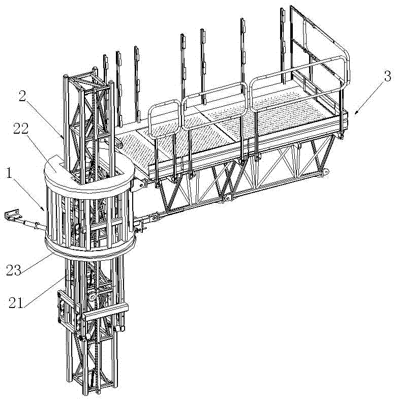
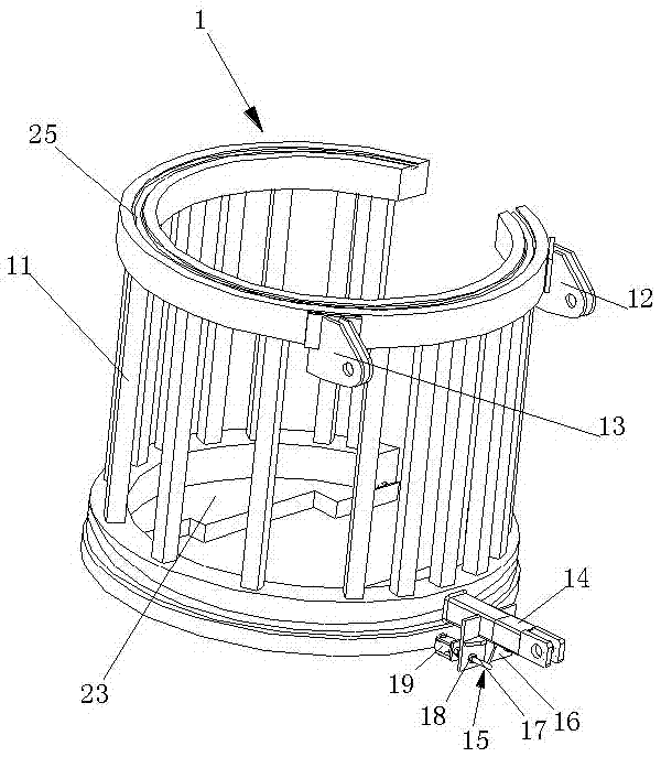
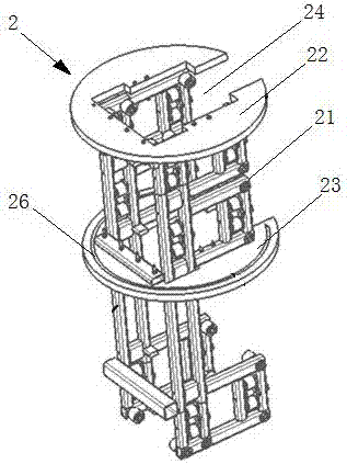
[0029] see Figure 1-3 , a rotatable bridge device, including a rotating mechanism 1, a climbing mechanism 2, an operating platform 3 and a driving mechanism 4; the climbing mechanism 2 includes a vertically arranged space bracket 21 and an upper end cover 22 and a lower end cover arranged in parallel and opposite up and down 23; The upper end cover 22 and the lower end cover 23 are provided with through holes 24, the upper end cover 22 and the lower end cover 23 are sleeved on the space support 21 through the through holes 24, and the upper end cover 22 and the lower end cover 23 are connected to the space support 21 through bolts respectively Connection; the rotating mechanism 1 includes a vertically arranged cylindrical frame 11 and a connecting part fixed on the frame 11. A gap is provided on the circumference of the frame 11 to facilitat...


PUM


Abstract

The invention relates to a rotatable bridge frame. The rotatable bridge frame comprises a rotating mechanism, a climbing mechanism, an operating platform and a driving mechanism. The climbing mechanism comprises a space support, an upper end cover and a lower end cover, wherein the space support is arranged vertically, and the upper end cover and the lower end cover are up-and-down opposite to each other; through holes are formed in both the upper end cover and the lower end cover, and the upper end cover and the lower end cover are arranged on the space support in a sleeving mode through the through holes and are detachably connected with the space support; the rotating mechanism comprises a frame and a connecting part, wherein the frame is in a cylindrical shape and arranged vertically, the connecting part is fixed to the frame, and the frame is arranged on the space support between the upper end cover and the lower end cover in a sleeving mode; the frame is fixedly connected with the operating platform through the connecting part; and the driving mechanism drives the frame to rotate around the space support. According to the rotatable bridge frame, angle adjustment can be conducted on high, constructing efficiency is effectively improved, and constructing safety is guaranteed.

Description

technical field [0001] The invention relates to a rotatable bridge frame, which belongs to the field of construction engineering. Background technique [0002] With the rapid economic growth and the rapid growth of urban population, the contradiction of decreasing urban construction land becomes more and more prominent. Super high-rise buildings have developed rapidly due to the advantages of less land, low cost of urban infrastructure, and can improve the appearance of the city. With more and more super high-rise buildings in modern engineering projects, the difficulty and quality requirements of construction technology are constantly increasing, especially when it comes to the construction of some irregular building appearances, the complexity and difficulty of construction technology management are getting higher and higher, especially Due to the limitation of geographical location and building construction site for exterior decoration, safety protection has become a majo...

Claims


Application Information

Patent Timeline
IPC IPC(8): E04G3/28E04G5/00
CPCE04G3/28E04G5/00E04G5/006E04G2003/283
Inventor 蔡宁建何文林荀名红李洪强付兵
Owner 福建建中建设科技有限责任公司
Why Eureka
Try Eureka